167
APPENDICES
A
Appendix 1 Details of I/O Signals
Appendix 1.1 Input signal
APPENDICES
Appendix 1 Details of I/O Signals
The following describes the details of the A/D converter module I/O signals assigned to the CPU module.
The I/O numbers (X/Y) described in Appendix 1are for the case when the start I/O number of the A/D converter module
is set to 0.
Appendix 1.1 Input signal
(1) Module READY (X0)
Module READY (X0) turns ON to indicate the preparation for the A/D conversion is completed after the power-on
or after the reset operation of the CPU module, and then the A/D conversion is proceeded.
In the following cases, Module READY (X0) turns off.
• In the offset/gain setting mode (In this case, the A/D conversion processing is executed)
• When a watch dog timer error occurs to the A/D converter module (In this case, the A/D conversion
processing is not executed)
(2) Warning output signal (X8)
Warning output signal (X8) turns ON when the process alarm has been detected.
(a) Process alarm
• Warning output signal (X8) turns ON when digital output values of the A/D conversion enabled channels
exceed the ranges set for CH1 Process alarm lower lower limit value (Un\G86) to CH4 Process alarm
upper upper limit value (Un\G101) after validating the alarm output setting (process alarm).
The ALM LED also turns on along with the on of the signal.
• Warning output signal (X8) turns OFF when the digital output values fall within the setting range for all the
A/D conversion enabled channels.
The ALM LED also turns off along with the off of the signal.
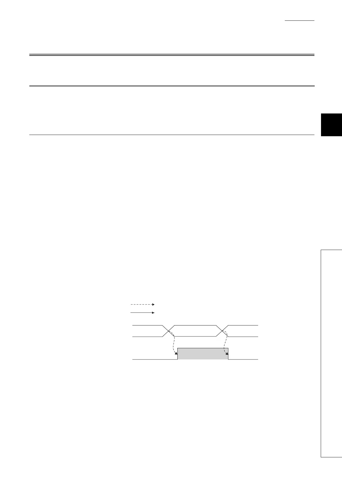
Warning output flag
(Process alarm)
(Un\G50)
Warning output signal
(X8)
Warning (process alarm)
00
Controlled by the A/D converter module
ON
OFF
Controlled by the program
 Loading...

