17
CHAPTER 2 PART NAMES
2
CHAPTER 2 PART NAMES
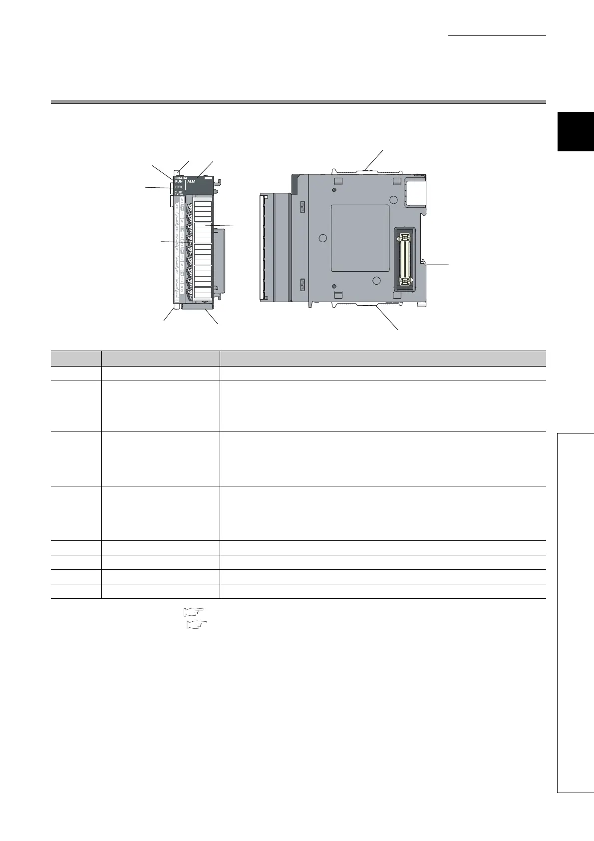
The following table shows part names of the A/D converter module.
*1 Error Code List ( Page 159, Section 11.4)
*2 Alarm Code List ( Page 163, Section 11.5)
Number Name Description
1) Module joint levers Levers for connecting modules
2) RUN LED (green)
Displays the operating status of the A/D converter module.
On: The module is operating normally.
Flashing: In the offset/gain setting mode
Off: The 5V power off or watchdog timer error has occurred.
3) ERR. LED (red)
Displays the errors and status of the A/D converter module.
On: an error has occurred except for error code: 112
*1
Flashing: Error code: 112 has occurred.
*1
Off: The module is operating normally.
4) ALM LED (red)
Displays the alarm status of the A/D converter module.
On: Alarm (process alarm) is occurring
*2
Flashing: Input signal error detection is occurring
Off: The module is operating normally.
*2
5) DIN rail hook A hook used to mount the module to a DIN rail
6) Terminal block 18-pin screw terminal block for connecting input signal lines of such as external devices
7) Terminal block cover Covers for preventing electric shock while the power is on
8) Serial number display Displays the serial number printed on the rating plate.
4)
1)
2)
1)
1)
5)
1)
3)
6)
7)
8)
 Loading...

