47
CHAPTER 6 INSTALLATION AND WIRING
6
6.4 External Wiring
6.4 External Wiring
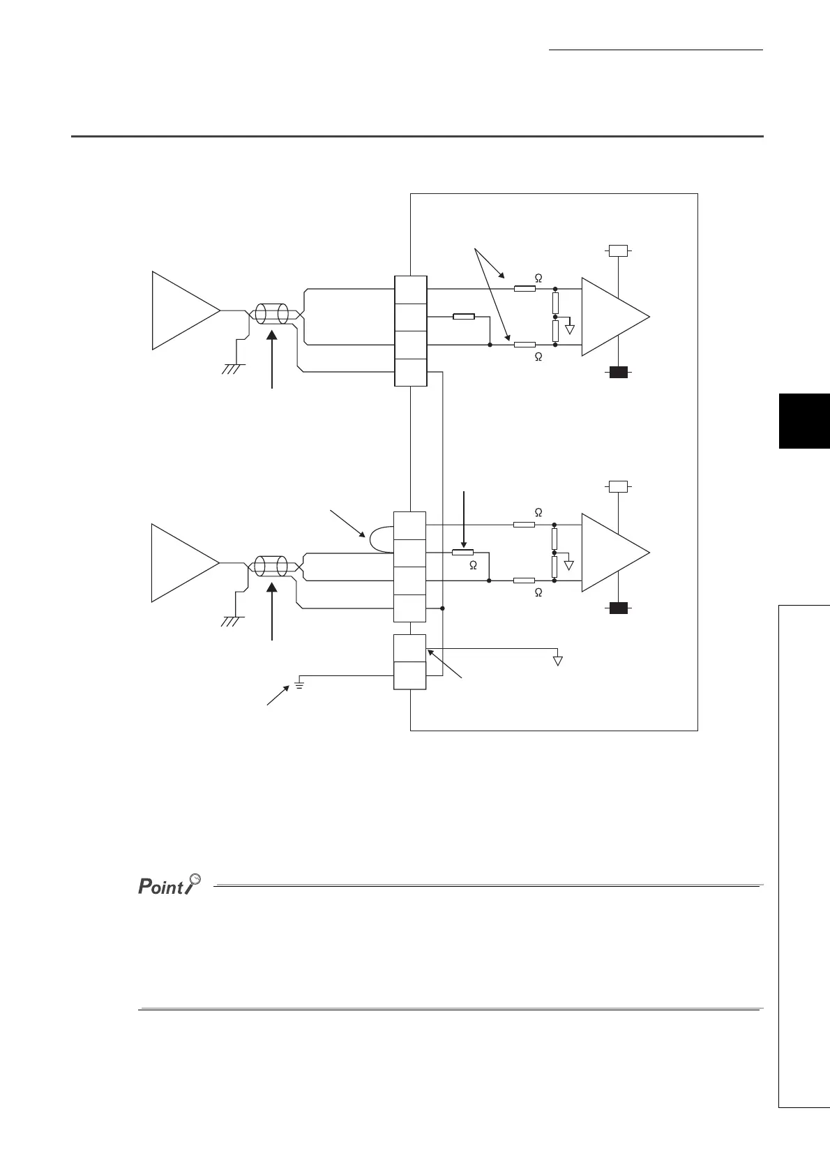
The following describes the external wiring.
*1 For the wire, use the shielded twisted pair cable.
*2 This indicates the input resistance of the A/D converter module.
*3 For the current input, always connect the terminals (V+) and (I+).
*4 If there are potential differences between the AG terminal and GND of the external device, connect the AG terminal to
the GND of the external device.
*5 Always connect the shielded wire for each channel to the shield terminal and ground the FG terminal.
In addition, ground the FG terminal of the power supply module.
In unused channels, if the circuit between two terminals is kept open, an undefined digital value may be output.
To prevent this phenomenon, perform any of the following measures.
● Set the A/D conversion enable/disable setting in the unused channel to disable.
Note that changing the A/D conversion enable/disable setting from A/D conversion enable to A/D conversion disable
reduces the conversion cycle.
● Short-circuit the input terminal (V+) and (V-) of the unused channel.
(1) For voltage input
Signal source -10 to 10V
(2) For current input
Signal source 0 to 20mA
Shield
*
1
*
2
*3
*
4
*
5
*
2
*
1
500k
500k
500k
250
500k
V+
I+
V-/I-
SLD
V+
I+
V-/I-
SLD
AG
FG
Shield
 Loading...

