181
APPENDICES
A
Appendix 2 Details of Buffer Memory Addresses
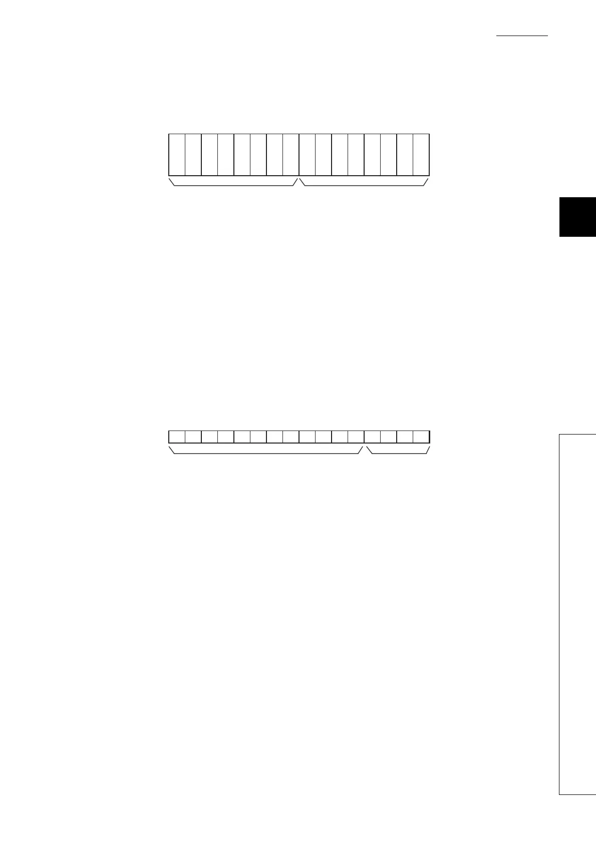
(17)Warning output flag (Process alarm) (Un\G50)
Alarms can be checked if the alarm is the upper limit alarm or lower limit alarm, for each channel.
(a) Warning output flag (Process alarm) (Un\G50) status
• When the value is out of the range specified in CH1 Process alarm lower lower limit value (Un\G86) to
CH4 Process alarm upper upper limit value (Un\G101), Warning output flag (Process alarm) (Un\G50)
corresponding to each channel is turned to alarm ON (1).
• When an error is detected in any A/D conversion enable or alarm output enable channels, Warning output
signal (X8) is also turned to ON.
(b) Clearing Warning output flag (Process alarm) (Un\G50)
• When the digital output value returns within the setting range, the flag is automatically cleared.
• When Operating condition setting request (Y9) is turned OFF → ON → OFF, it is cleared.
(18)Scaling enable/disable setting (Un\G53)
Set whether the scaling is enabled or disabled, for each channel.
(a) Enabling the setting
Turn OFF → ON → OFF Operating condition setting request (Y9) to enable the setting.
(b) Default value
All channels are set to disable (1) as the default value.
00000000
CH1CH2
b15 b14 b13 b12 b11 b10 b9 b8 b7 b6 b5 b0b1b2b3b4
CH1CH2CH3CH4 CH4 CH3
0: Normal
1: Alarm on
Data for b4 to b15 are fixed to "0".
upper limit
value
lower limit
value
upper limit
value
upper limit
value
upper limit
value
lower limit
value
lower limit
value
lower limit
value
00000000000
CH1CH2CH3CH4
0
b15 b14 b13 b12 b11 b10 b9 b8 b7 b6 b5 b0b1b2b3b4
0: Valid
1: Invalid
Data for b4 to b15 are fixed to "0".
 Loading...

