184
(22)CH Input signal error detection setting value (Un\G142 to Un\G145)
Set the setting value to detect an input analog value error for each channel.
For details on the input signal error detection function and input signal error detection extension function, refer to
the following.
• Input signal error detection function ( Page 69, Section 8.7)
• Input signal error detection extension function ( Page 74, Section 8.8)
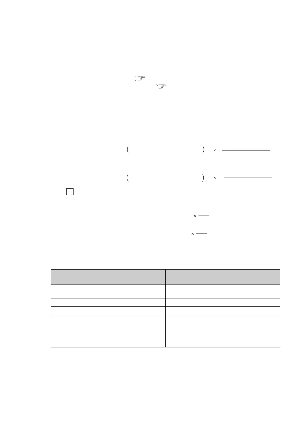
(a) Setting procedure
• Setting range is 0 to 250 (0 to 25.0%). Set in increments of 1 (0.1%).
• The input signal error detection upper and lower limit values are calculated as follows based on the input
signal error detection setting value. The calculating input signal error detection upper and lower limit
values will be different depending on the input range to be used.
• Conditions vary as follows depending on the setting in Input signal error detection extension setting
(Un\G27).
(b) Enabling the setting
Turn OFF → ON → OFF Operating condition setting request (Y9) to enable the setting.
(c) Default value
All channels are set to 5% (50).
[Input signal error detection upper limit value]
[Input signal error detection lower limit value]
When the input signal error detection setting value is set to 100 (10%)
Range to be used: 4 to 20mA
The upper and lower limit values of input signal error detection are as follows:
Input signal error detection extension setting
(Un\G27)
Detection condition
Lower upper limit detection (1)
At the input signal error detection upper limit value or the
input signal error detection lower limit value
Lower limit detection (2) At the input signal error detection lower limit value
Upper limit detection (3) At the input signal error detection upper limit value
Disconnection detection (4)
• In 2mA or less, or 0.5V or less
• The setting for CH Input signal error detection setting
value (Un\G142 to Un\G145) is ignored.
• Input range other than 4 to 20mA (extended mode) or 1 to
5V (extended mode) cannot be used.
=
Gain value of
each range
+
-
Offset value of
each range
Gain value of
each range
Input signal error
detection setting value
1000
Input signal error
detection setting value
1000
=
Lower limit value
of each range
-
-
Offset value of
each range
Gain value of
each range
Ex.
= 20 + (20 - 4)
Input signal error
detection upper limit value
100
1000
= 21.6mA
= -4 - (20 - 4)
Input signal error
detection lower limit value
100
1000
= -2.4mA
 Loading...

