REASSEMBLY OF BASIC ENGINE
7-12
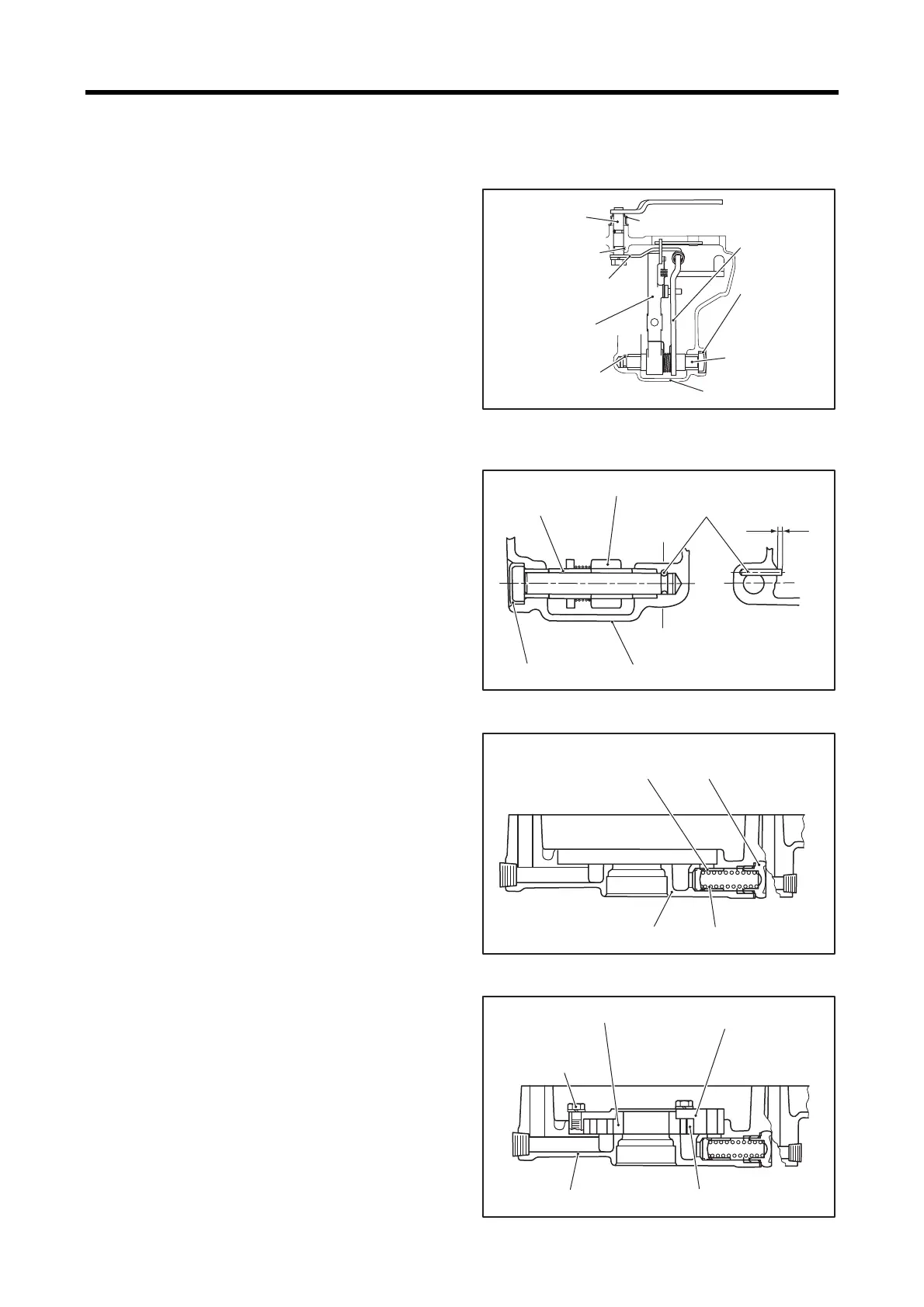
2.8 Installing speed control lever and
governor shaft
(1)
Insert the governor shaft into the gear case with the
governor lever and the tension lever positioned in
place.
(2) Drive the grooved pin into the gear case.
(3) Drive new sealing cap into the gear case.
(4) Thoroughly apply Alvania Grease #2 or #3 to the
governor shaft cover.
(5) Install new O-ring on the speed control lever and insert
it into the gear case through the governor shaft.
(6) Drive the grooved pin into the gear case.
(7) Install the governor spring lever.
Note: Install the governor spring lever to the speed control
lever with the minimum assembling angle.
Installing speed control lever and
governor shaft
Reassembling speed control lever
2.9 Installing relief valve
Insert the relief plunger and relief spring into the gear case,
and tighten the plug to the specified torque.
Installing relief valve
2.10 Installing oil pump
Install the oil pump inner gear, oil pump outer gear and oil
pump housing to the gear case, and tighten the bolts to the
specified torque.
Installing oil pump
Speed control
lever
Grooved pin B
Grooved pin A
Governor spring lever
Governor lever
Gear case
Governor shaft
Governor shaft cover
Tension lever
Sealing cap
Grooved pin
Protrusion
approx. 2 mm
[0.08 in.]
Tension
lever
Governor lever
Sealing cap
Gear case
Section AA
㧭
㧭
Plug
Relief spring
Gear case
Relief plunger
39.2 to 49.0 N㨯m
{4.0 to 5.0 kgf㨯m}
[28.9 to 36.2 lbf㨯ft]
Oil pump housing
Oil pump outer gear
Gear case
Oil pump inner gear
7.8 to 9.8 N㨯m
{0.8 to 1.0 kgf㨯m}
[5.8 to 7.2 lbf㨯ft]
 Loading...


