ELECTRICAL SYSTEM
12-23
2.6 Inspection before disassembling starter (M002T66071 (24V-3.2kW))
2.6.1 Inspecting pinion clearance
&$87,21
Do not apply current continuously for longer than 10
seconds.
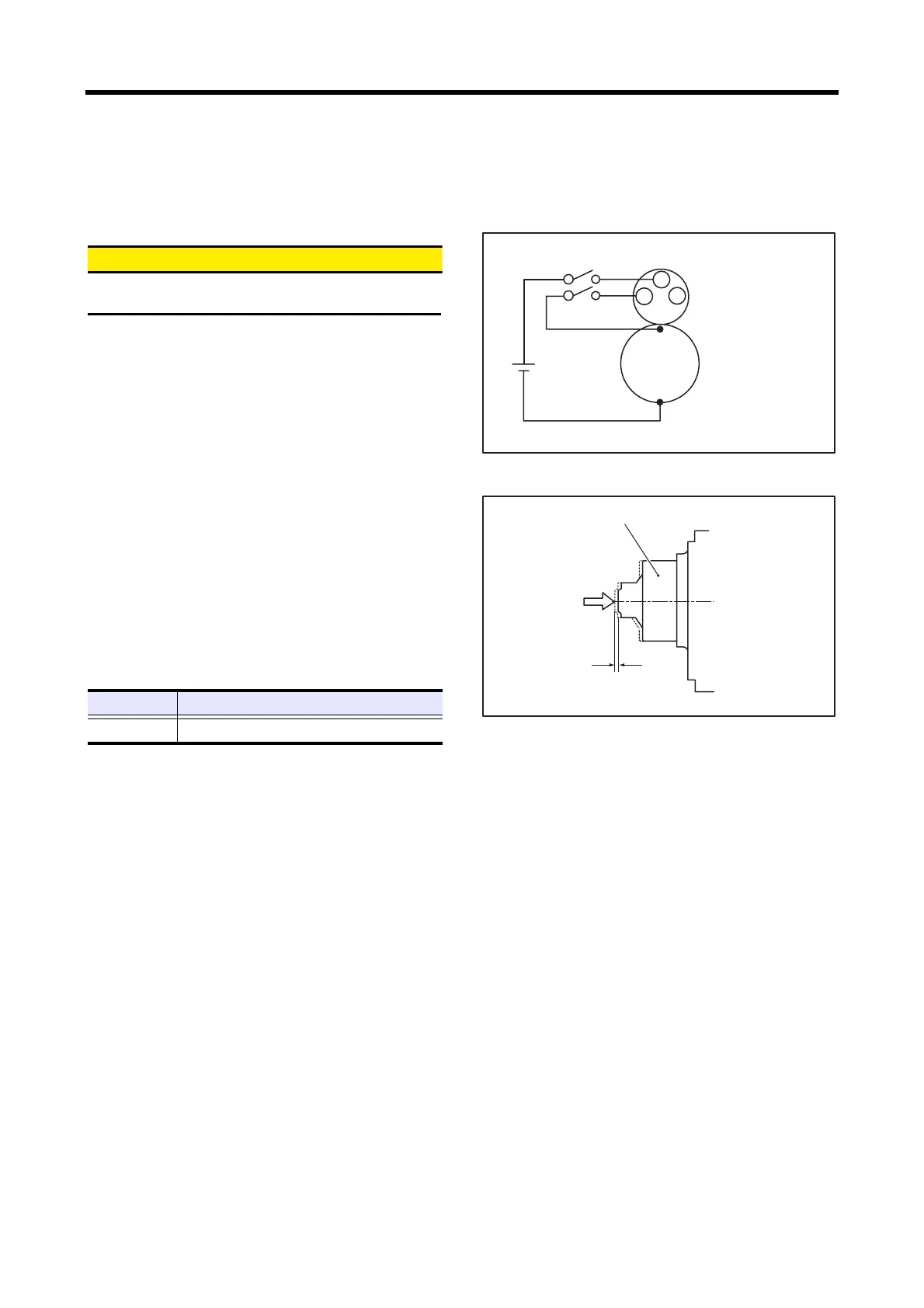
(1) Connect the starter to the circuit as shown in the
illustration.
(2) When the switches SW1 and SW2 are turned ON, the
pinion springs out to the cranking position and the
armature rotates.
(3) Turn the switch SW2 OFF to stop the rotation of the
armature.
(4) Gently push back the pinion in the out position with a
finger and measure the distance over which the pinion
has returned (movement amount).
(5) If the measured value is out of the standard, increase or
decrease the number of packings between the magnetic
switch and the front bracket for adjustment, or replace
the lever with a new one.
Note: When the number of packings is increased, the pinion
clearance becomes small.
Wiring during inspection of pinion clearance
Inspecting pinion clearance
Item Standard
Pinion gap 0.5 to 2.0 mm [0.0197 to 0.0787 in.]
59
59
Battery
24V
㧮
㧿
㧹
Disconnect the lead
with a terminal
connected to
terminal M.
Pinion
Gently push back
the pinion.
Pinion clearance
0.5 to 2.0 mm [0.0197 to 0.0787 in.]
 Loading...


