Rear Panel Cha
ter Three: Overview
32
Electrical Connections
Tables 8 through 14, on the following pages, list each connector’s pinout as well as
corresponding MKS cable numbers.
Note
1.
An overall metal braided shielded cable, properly grounded at both
ends, is required to meet CE specifications.
2.
To order a metal braided shielded cable, add an “S” after the cable
type designation. For example, to order a standard cable to connect
the 651 controller to a Type 627 transducer, use part number
CB259-5-10; for a metal braided, shielded cable use part number
CB259S-5-10.
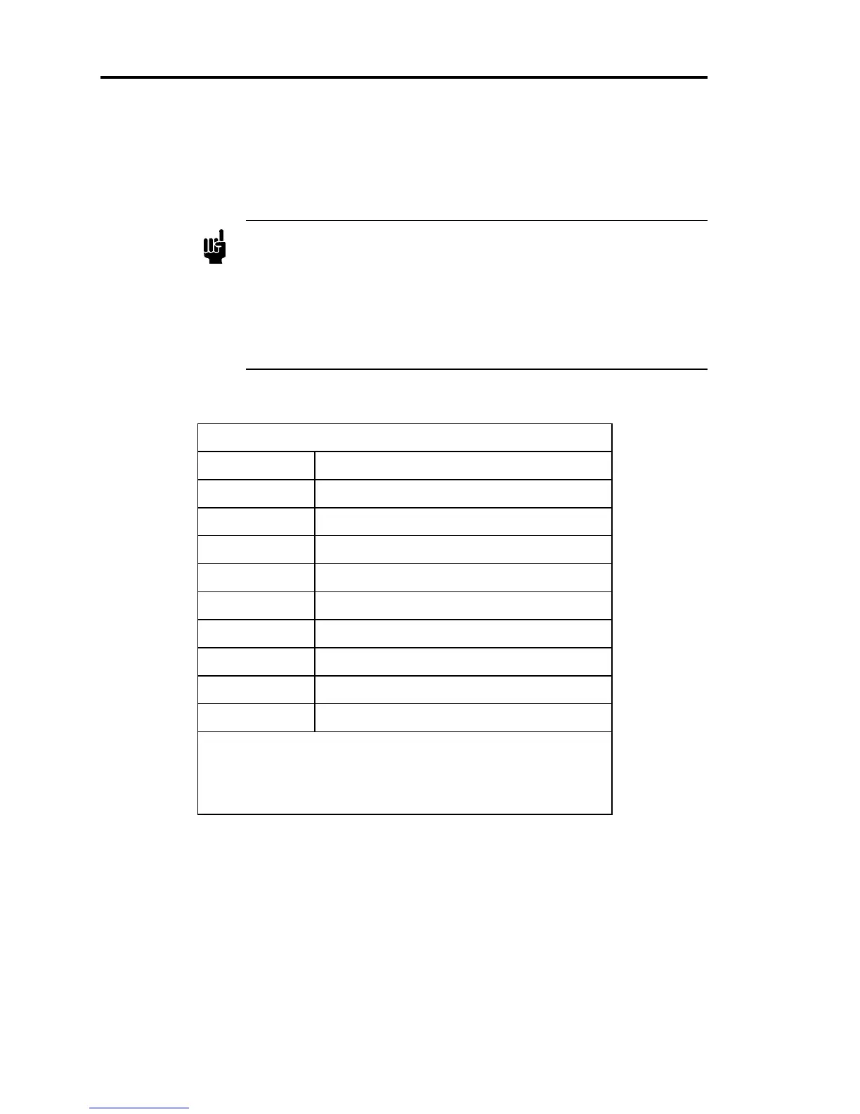
Serial RS-232 Interface Connector Pinout
Pin Number Function
1 No connection
2 Transmit data
3 Receive data
4 No connection
5 Digital ground
6 Reserved
7 Reserved
8 No connection
9 No connection
A
Reserved
pin assignment means that the pin has an internal
connection and may be assigned a function in the future. The
No Connection
pin assignment refers to a pin with no internal
connection.
Table 8: Serial RS-232 Interface Connector Pinout