Appendix A: Product Specifications
113
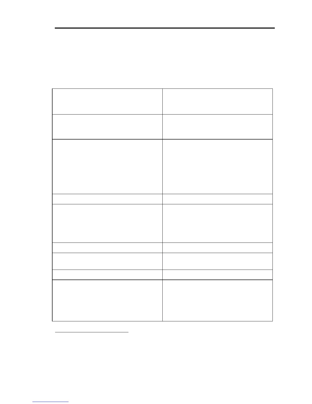
Appendix A: Product Specifications
Ambient temperature
15
°
to 40
°
C (60
°
to 104
°
F)
15
°
to 35
°
C (60
°
to 95
°
F) with optional
valve failsafe battery backup
Analog output signal
Position
Pressure
0 to 5 Volts or 0 to 10 Volts, selectable
0 to 100% F.S. pressure, same range as sensor
CE Compliance
Electromagnetic Compatibility
1
Low-Voltage Requirements
Installation Category
Pollution Degree
Product Safety Requirements
EMC Directive 89/336/EEC
Low-Voltage Directive 73/23/EEC
II, according to EN 61010-1
2, according to IEC 664
Product Safety Directive 92/59/EEC
Controller repeatability ±0.1% of F.S.
Connectors
2
Valve
I/O
Transducer
RS-232 Serial Communications
9-pin Type “D” female
37-pin Type “D” female
15-pin Type “D” female
9-pin Type “D” male
Display 2 line LCD with 4½ place readout
Display units Torr, mTorr, mbar, µbar, Pascal, kPa,
cmH
2
O, inH
2
O
External set point signal 0 to 5 Volts or 0 to 10 Volts, selectable
Fuses
Low power unit: 90 to 132 VAC
180 to 264 VAC
High power unit: 90 to 132 VAC
180 to 264 VAC
0.63A (T), 250V, 5 x 20 mm
0.315A (T), 250V, 5 x 20 mm
1.25A (T), 250V, 5 x 20 mm
0.63A (T), 250V, 5 x 20 mm
1
An overall metal braided shielded cable, properly grounded at both ends, is required during use.
2
Interconnecting cables between the Type 651 and the valve, sensor, and serial communications are
available at an additional charge. Please consult factory for ordering information. Necessary adapter
cables are included when retrofitting MKS Type 152, 252, and 652 controllers.