Product Location and Requirements Cha
ter Two: Installation
22
Optional Equipment:
•
651-K1 accessory kit (includes an I/O connector for the rear panel of the unit, a connector
cover for the I/O connector, and a screwlock assembly for the I/O connector cover)
•
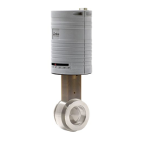
Cables for supported sensors and the MKS Types 253 or 653 valves
•
RM-13 or RM-14 rack mount option
•
Valve failsafe battery backup (installed in the unit at the factory)
•
MKS RS-232 Serial Communications Cable (CB651-10-10)
Note
1.
An overall metal braided shielded cable, properly grounded at both
ends, is required to meet CE specifications.
2.
To order a metal braided shielded cable, add an “S” after the cable
type designation. For example, to order a standard cable to connect
the 651 controller to a Type 627 transducer, use part number
CB259-5-10; for a metal braided, shielded cable use part number
CB259S-5-10.
Product Location and Requirements
The Type 651 unit meets the following criteria:
•
POLLUTION DEGREE 2 in accordance with IEC 664
•
Transient overvoltages according to INSTALLATION CATEGORY II
Operating Environmental Requirements
•
Ambient Operating Temperature: 15
°
to 40
°
C (60
°
to 104
°
F)
15
°
to 35
°
C (60
°
to 95
°
F) with optional valve
failsafe battery back-up
•
Main supply voltage fluctuations must not exceed
±
10% of the nominal voltage
•
Ventilation requirements include sufficient air circulation
•
Connect the power cord into a grounded outlet
Safety Conditions
The 651 controller poses no safety risk under the following environmental conditions:
•
Altitude: up to 2000 m
•
Maximum relative humidity: 80% for temperatures up to 31
°
C, decreasing linearly to
50% at 40
°
C