Appendix D: Type 651 Displayless Unit RS-232 Confi
uration
121
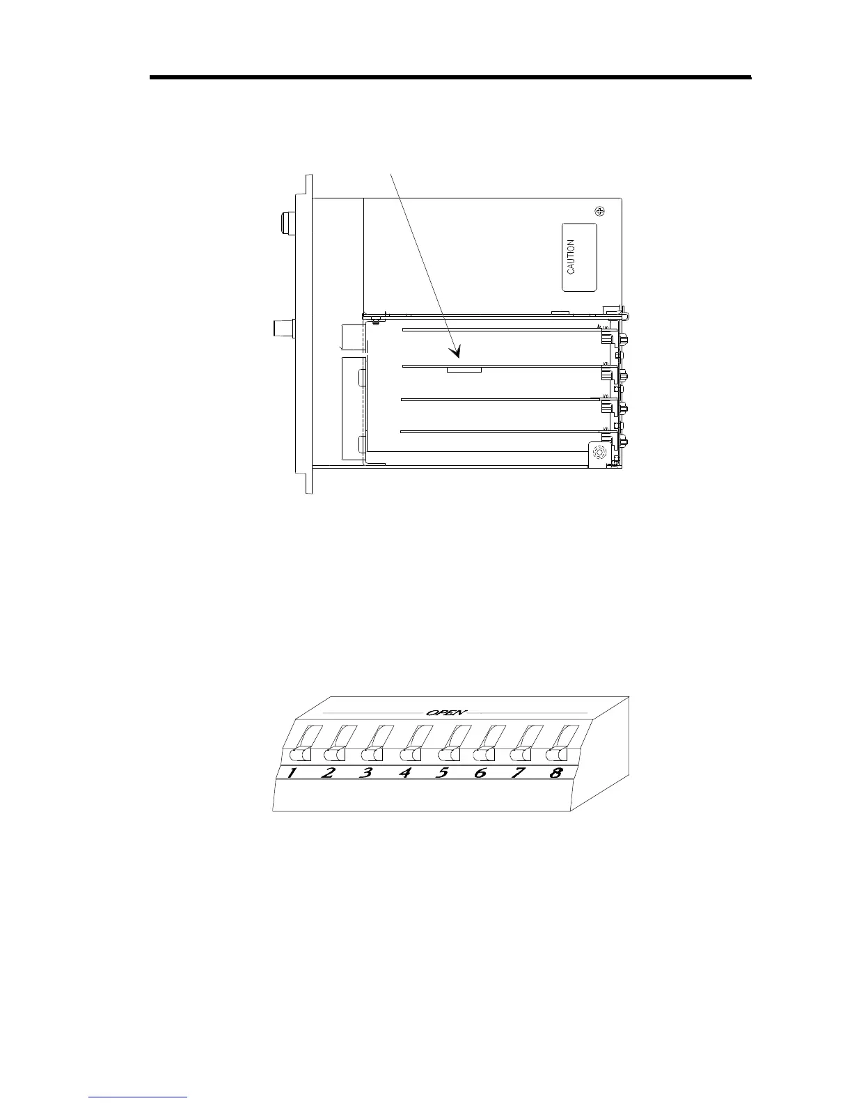
Dipswitch Bank on I/O Board
Figure 15: Dipswitch Bank Location (Top View)
The dipswitch bank is located on the I/O board, shown in Figure 15. You can also identify the
I/O board by locating the I/O connector on the rear panel (refer to Figure 4, page 31).
Figure 16, shows an enlarged view of a dipswitch bank. The switches in the dipswitch bank are
numbered from 1 to 8. The dipswitch bank has the word
OPEN
written on it. To set a dipswitch
to open, push it toward the OPEN label. To set a dipswitch to closed, push it away from the
OPEN label. For example, in Figure 16 all of the switches are closed.
Figure 16: Example of Dipswitch Bank