Rear Panel Cha
ter Three: Overview
34
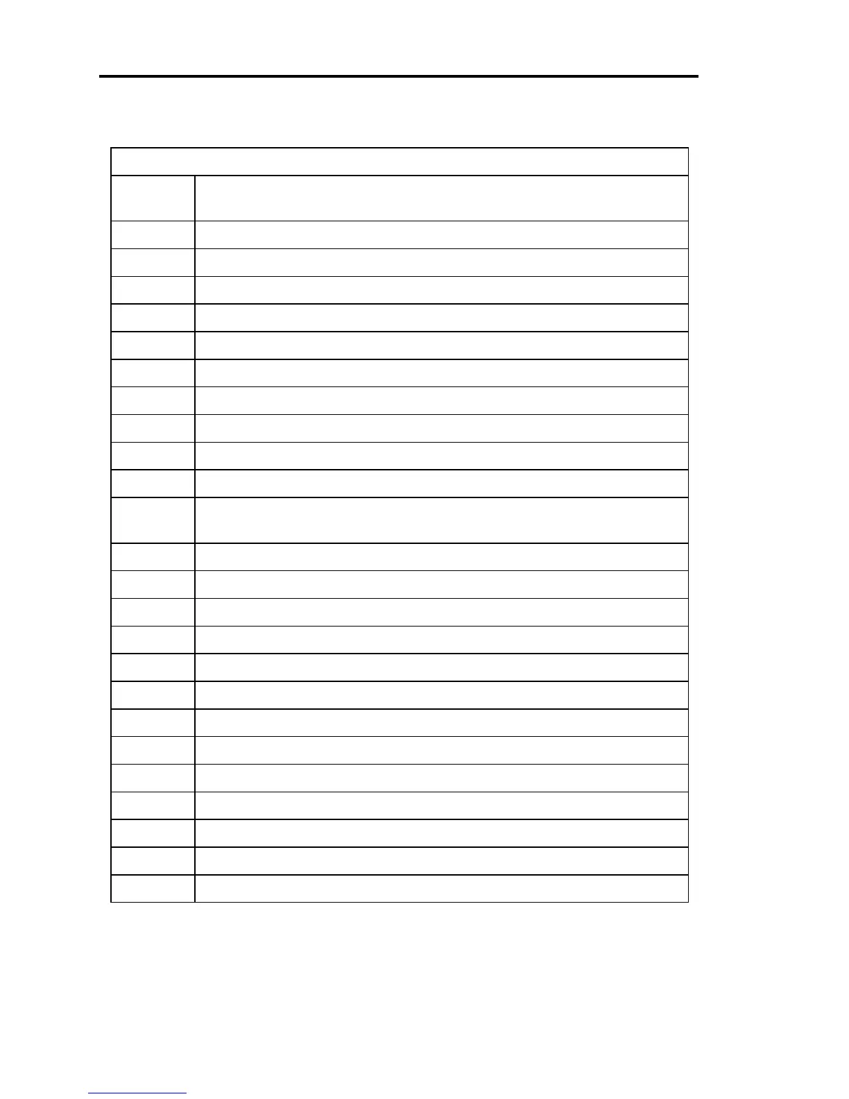
I/O Connector Pinout
Pin
Number
Function
1 PLO relay #1 - NC contact
2 PLO relay #1 - NO contact
3 PLO relay #2 - NC contact
4 Digital ground
5 Learn system (low)
6 Hold
both
pin 6 and pin 11 low to select analog set point with position control
7 Softstart (low)
8 Close valve (low)
9 Reserved
10 Analog set point ÷ 10
11 Hold
only
pin 11 low to select analog set point with pressure control
Hold
both
pin 6 and pin 11 low to select analog set point with position control
12 Select set point E (low)
13 Select set point D (low)
14 Select set point C (low)
15 Select set point B (low)
16 Select set point A (low)
17 Reserved
18 Reserved
19 Valve open status (hi = open)
20 PLO relay 1 - common contact
21 PLO relay 2 - common contact
22 PLO relay 2 - NO contact
23 Valve closed status (hi = closed)
24 Reserved
Table 10: I/O Connector Pinout
(Continued on next page)