Digital Logic Control Cha
ter Six: Remote O
eration
90
Digital Logic Control
Digital and analog control of the 651 unit is accomplished via the I/O connector located on the
rear panel. Refer to Table 10, page 34, for the pinout of the I/O connector.
Note
Any RS-232 command takes priority over digital logic commands. For
example, a valve being held closed with a digital logic command can be
commanded to control to the level of set point A with the
D1
command.
Digital
inputs
and
outputs
are designed to interface with low power TTL and CMOS logic
families. They also include additional components to protect against damage from ESD or
transient voltages. A brief description of the digital circuitry of the I/O board is provided in the
following section.
I/O Board Digital Circuitry
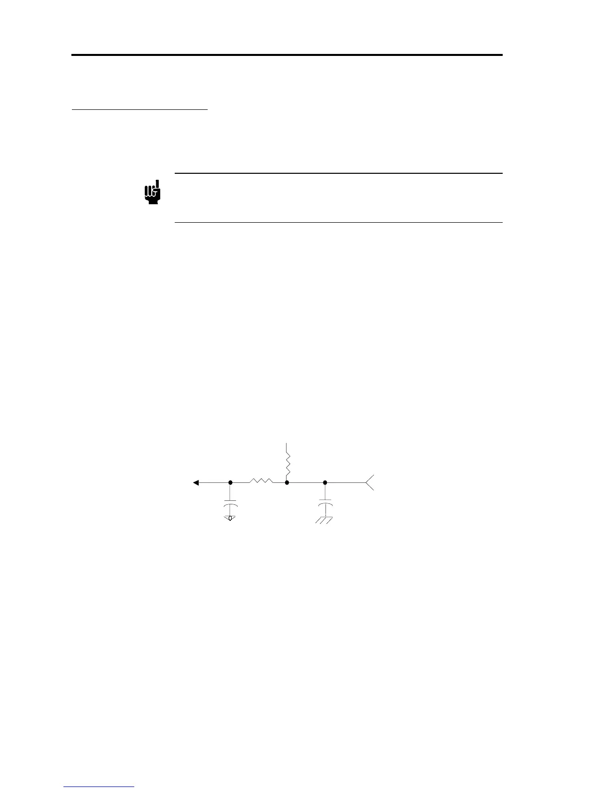
The I/O board contains 16 type 74HC
inputs
. To select an input function, pull the appropriate
input pin low (0 to 0.8 Volts). The TTL low signal is “level sensitive” meaning that once the
signal is held low, the 651 unit may take up to 50 milliseconds to recognize the command. The
line must be held low
continuously
for the 651 unit to use the selected parameters. Once the
signal goes high, the instrument will default back to the state associated with the high signal
within 50 milliseconds. Each input consists of a single pole filter and pull-up resistor as shown
in Figure 6.
µ
Di
ital Ground
To input port
74HC541)
I/O Connector
4.7k
0.01
FD
µ
0.01
FD
4.7k
+5 V
Figure 6: I/O Board Digital Input Circuitry