Replacing the Battery-Backed Memory Module Cha
ter Seven: Batter
-Backed Memor
Module
98
Removing the CPU Board and Memory Module
1. Locate the CPU board.
It is labeled on the rear panel as the Serial Interface connector (in slot 1).
2. Remove the screw to the left of the connector.
3. It may be necessary to remove the clamping spring that holds the card cage to the power
supply. If so, use needle-nose pliers or a screwdriver to pull the clamping spring straight
back and out.
4. Grasp each end of the board and rock it until it loosens from its position. Lift the board up
and out of the unit.
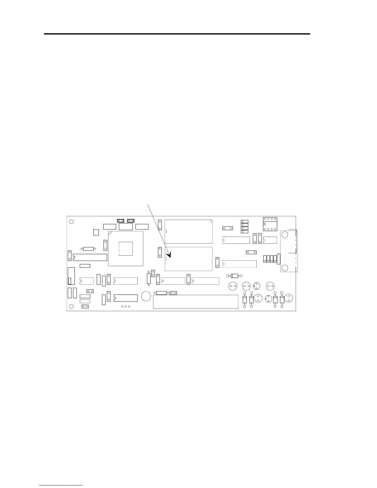
5. Figure 8 provides the location of the battery-backed memory module on the CPU board.
D13
D12
D11
D10
R13R12
J3
R11
R10 C27
C26
R9
D9
D8
D7
D6
C25
U5
D5D4C23
E3
E2
E1
U14
JP3JP2 S1
D3
R4
D2D1
Y1
C11
C10
C9
C8C1
C22
C21
C20
C19 C18
C17
C16
C15
C14
C13
C7
C4
C5
C6
C3
C2
R6
R5
R3
R2
R1
U13
U12
U11
U10
U9
U8
U7
U6
U4
U3
U2
U1
J1
J2
1
1
1
+
+
+
+
+
Batter
-backed
RAM module
Figure 8: Location of the Battery-backed RAM Module
6. Use needle-nose pliers, a screwdriver, or an IC puller to remove the memory module
from its socket.