RS-232 Configuration A
endix D: T
e 651 Dis
la
less Unit
122
Dipswitch Bank Settings
The dipswitch settings control the RS-232 communications parameters. When you receive your
651 controller, the unit is set up with the initial dipswitch settings listed in Table 23.
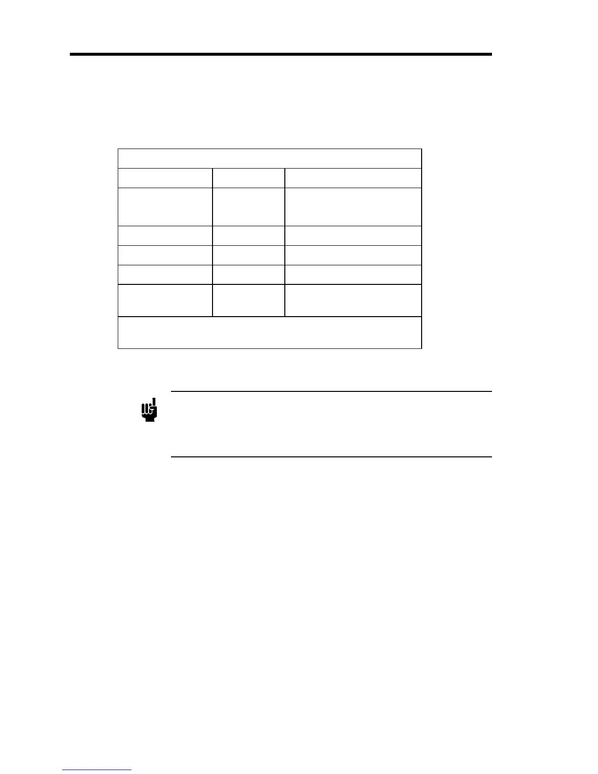
Default Dipswitch Settings
Dipswitch Setting Function
Switch 1, 2, 3 Closed 9600 Baud Rate
Switch 4 Open
Switch 5 Closed Parity - None, 8 data bits
Switch 6 Closed Reserved*
Switch 7 Closed Reserved*
Switch 8 Closed End-of-Line Delimiter
CRLF
* The “Reserved” pin assignmnet refers to a pin with an internal
connection which may be assigned a function in the future.
Table 23: Default Dipswitch Settings
Note
Parity and data bit setting are dependent. You may select either no parity
with 8 data bits or even parity with 7 data bits.
There is no stop bit setting. RS-232 communications uses 1 stop bit
under all circumstances. This setting
cannot
be changed.
If the initial settings, listed in Table 25, page 125, are not appropriate for your application, refer
to Table 24, page 123, for switch settings you can use to change the baud rate, parity and data
bits, and end-of-line delimiter.