Disassembly/Reassembly Procedures: Radio Disassembly Sec 1: 8-19
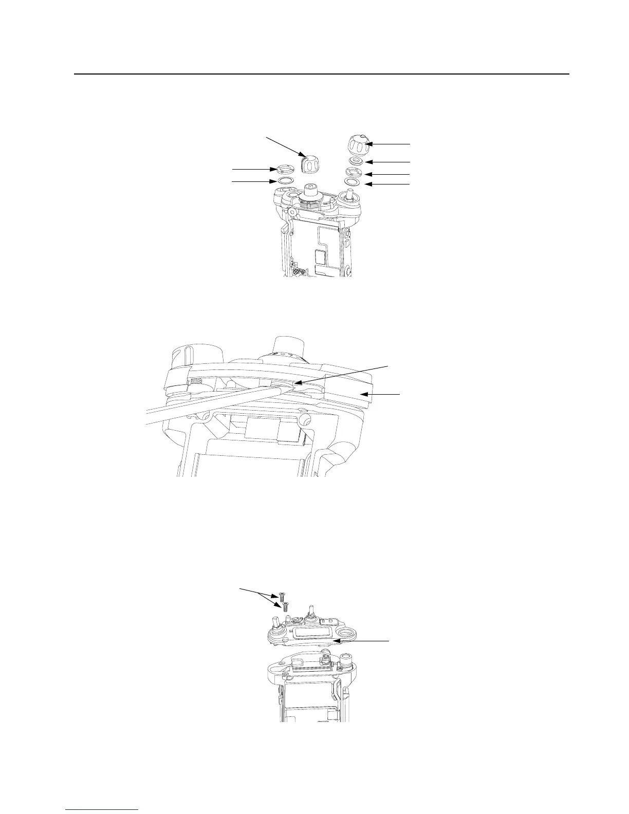
Figure 8-25. Remove Knobs and Fastener Hardware
iv. Gently lift the Control Top Bezel Assembly (11) and with the aid of the Black Stick, pop
the Secure Lever (14) off the Frequency shaft as shown in Figure 8-26.
Figure 8-26. Remove Control Top Bezel Assembly
8.7.9 Removal of the Control Top Assembly (J)
i. Use a Torx Plus IP8 bit to remove the two Control Top Screws (31). See Figure 8-27.
NOTE: Ensure the Control Top flex is disconnected from the VOCON Board (G, N) to
prevent damage to the flex or connector.
Figure 8-27. Remove Control Top Assembly (9)
Volume Knob (12)
Torque Adder (15)
Volume Spanner Nut (17)
Frequency Knob (13)
Antenna Spanner Nut (19)
Antenna Washer (18)
Volume Washer (16)
Secure Lever (14)
Control Top Bezel Assembly (11)
Control Top Assembly (J)
Control Top Screws (31)

 Loading...


