Sec 1: 3-2 Basic Theory of Operation: Analog Mode of Operation
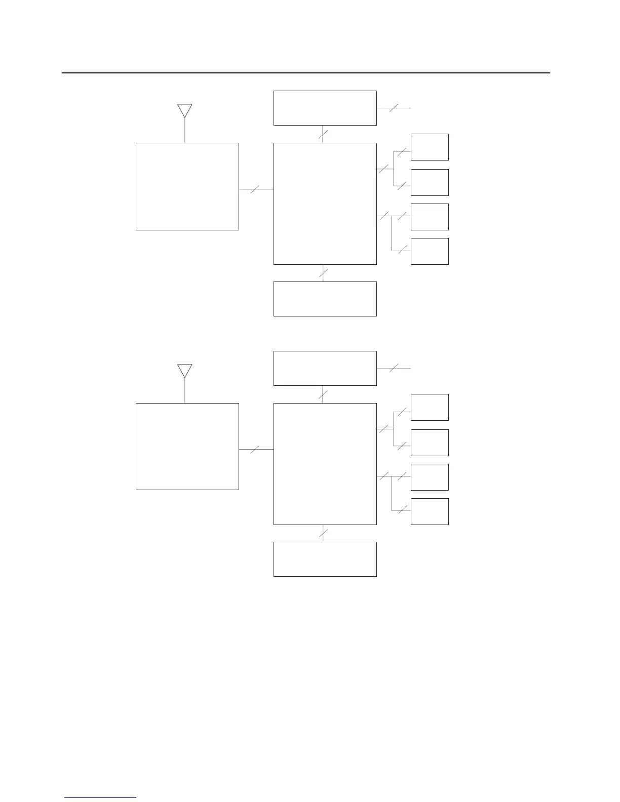
Figure 3-1. APX 7000 Overall Block Diagram (VOCON Board MNCN6200)
Figure 3-2. APX 7000 Overall Block Diagram (VOCON Board MNCN6202)
3.2 Analog Mode of Operation
This section provides an overview of the analog mode receive and transmit theory of operation.
3.2.1 Receiving
The RF signal is received at the antenna and is routed through the Auxiliary and Multi Switch (SP3T)
ICs. The latter contains a switchable attenuator that is enabled at predetermined RF power
thresholds present at the antenna port. The output of the Multi-switch IC is applied to the first SPST
band select switch to select the either the VHF or 700,800 bands (see Figure 3-3), UHF1 or 700,800
bands (see Figure 3-4), VHF/UHF1 bands (see Figure 3-5), UHF2 or 700,800 bands (see Figure 3-6)
and VHF or UHF2 bands (see Figure 3-7).
Expander
External accessory connecto
Board
External antenna
Front display
Transceiver VoCon
Keypad
Board Board
Top display
Controls top
Option
Board
40
60
14
60
40
20
50 20
30
60
Antenna
Expander
External accessory connecto
Board
External antenna
Front display
Transceiver VoCon
Keypad
Board Board
Top display
Controls top
Option
Board
40
60
14
80
50
30
50 20
30
60
Antenna

 Loading...


