Sec 2: 5-2 Performance Checks: Top-Display Version Radio Test Mode
Initial equipment control settings should be as indicated in Table 5-1 and should be the same for all
performance checks and alignment procedures, except as noted.
5.2 Top-Display Version Radio Test Mode
This section provides instructions for performing tests in non-display radio test mode.
5.2.1 Access the Test Mode
To enter the non-display radio test mode:
1. Turn the radio on.
2. Within 10 seconds after the top red LED turns off, press Side button 2 five times in
succession.
3. Do one of the following:
•Press the Top Side Button to put the radio into the Control Top and Keypad test mode.
Go to “5.2.3 Control Top Test Mode” below.
NOTE: Each press of the Top Side Button toggles between Control Top and Keypad test
mode (non-display radio) and RF test mode (non-display radio).
• Press the Top Button (Orange button) to put the radio into the RF test mode. Go to “5.2.2
RF Test Mode” below.
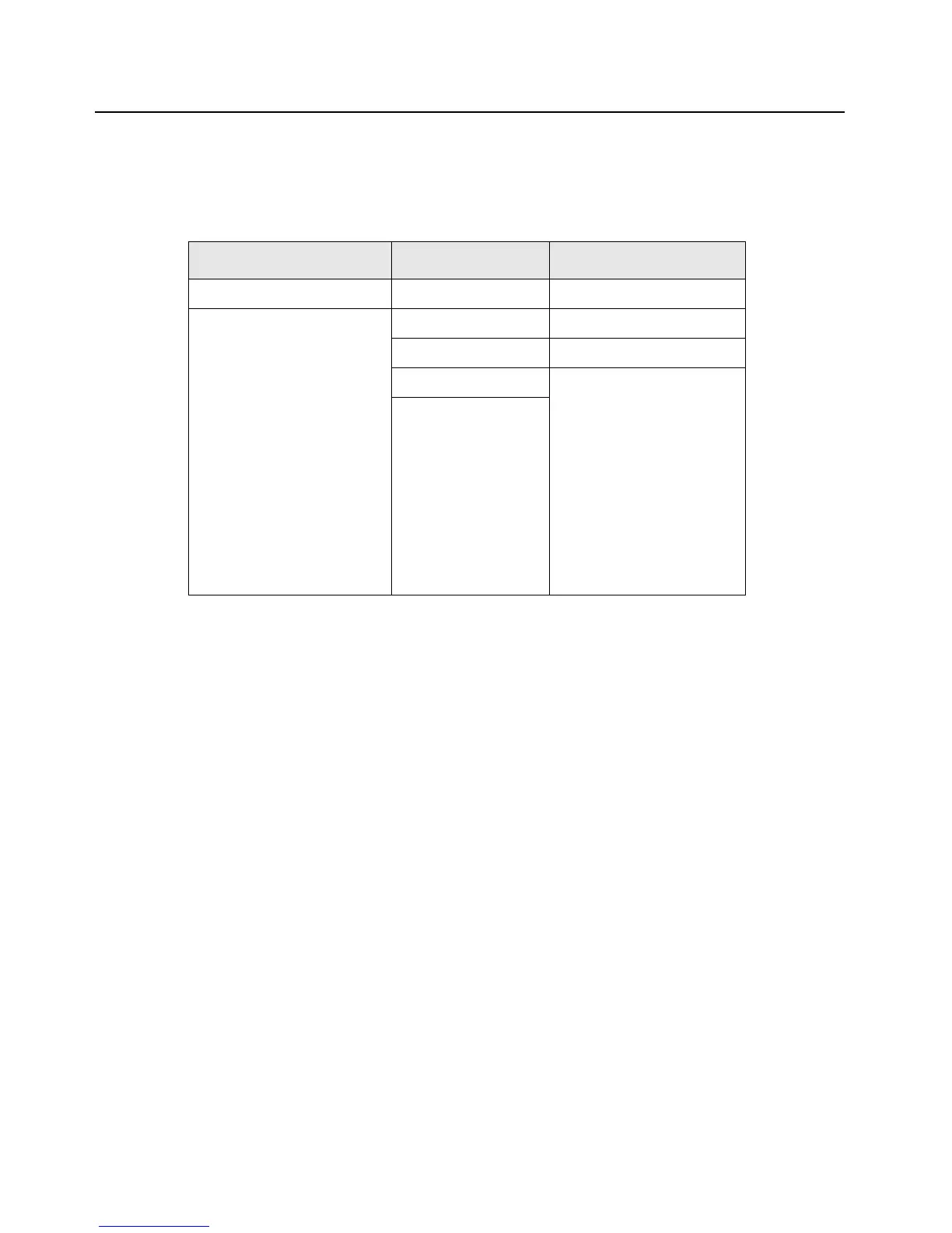
Table 5-1. Initial Equipment Control Settings
System Analyzer Test Set Power Supply
Monitor Mode: Standard* Spkr/Load: Speaker Voltage: 7.5 Vdc
Receiver Checks
RF Control: GEN
Output Level: -47 dBm
Modulation: 1kHz tone
@3 kHz deviation
Frequency: Set to selected
radio RX frequency
Meter: AC Volts
Transmitter Checks
RF Control: MONITOR
Frequency: Set to selected
radio TX frequency
Meter: RF Display
Modulation Type: FM
Attenuation: 20 dB
PTT: OFF (center) DC On/Standby: Standby
Meter Out: RX Volt Range: 10 Vdc
Opt Sel: ON Current: 2.5 Amps
* Use “PROJ 25 STD” if testing ASTRO Conventional channels.

 Loading...


