Sec 2: 3-2 Basic Theory of Operation: Analog Mode of Operation
3.2 Analog Mode of Operation
This section provides an overview of the analog mode receive and transmit theory of operation.
3.2.1 Receiving
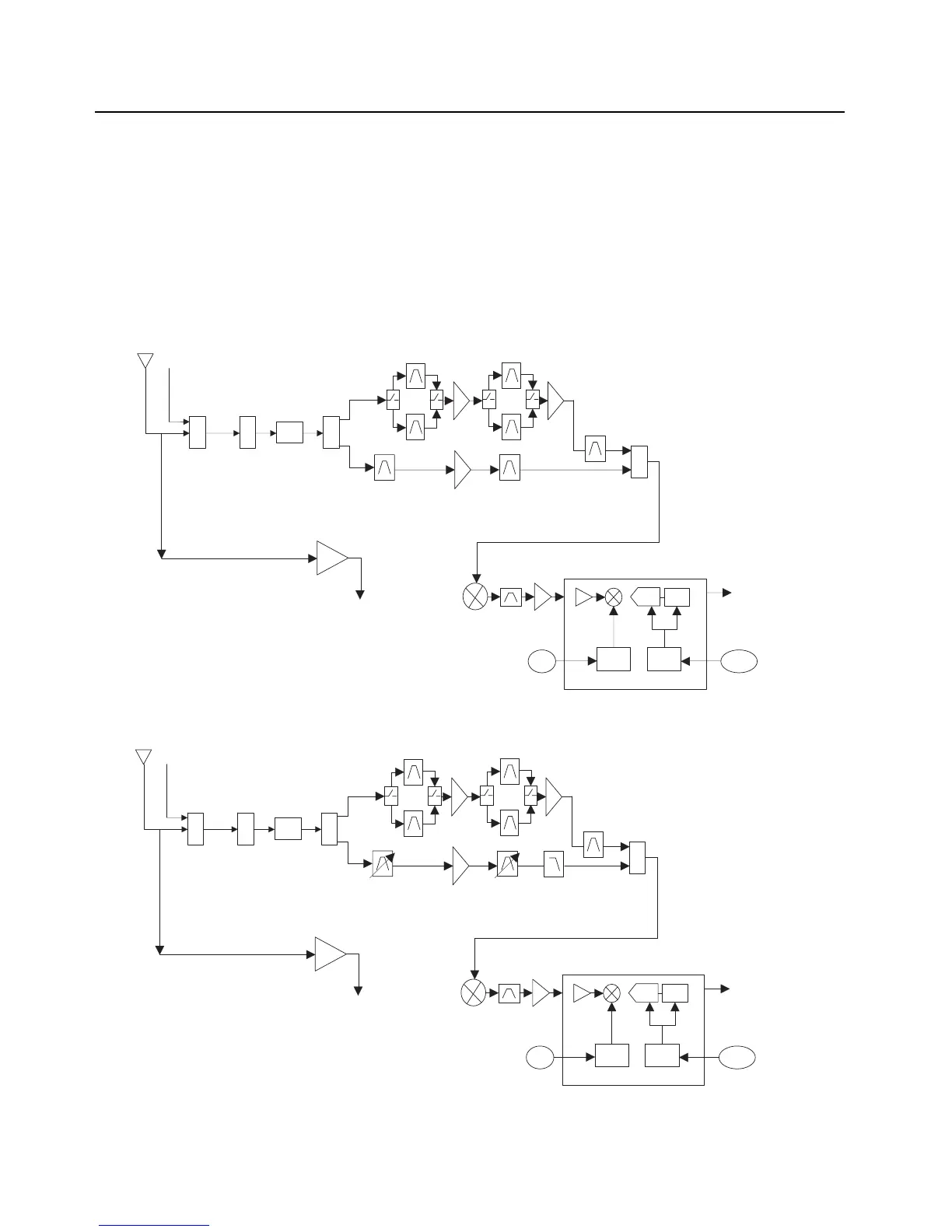
The RF signal is received at the antenna and is routed through the Auxiliary and Multi Switch (SP3T)
ICs. The latter contains a switchable attenuator that is enabled at predetermined RF power
thresholds present at the antenna port. The output of the Multi-switch IC is applied to the first SPST
band select switch to select the either the VHF or 700,800 bands (see Figure 3-2), UHF1 or 700,800
bands (see Figure 3-3), VHF/UHF1 bands (see Figure 3-4), UHF2 or 700,800 bands (see Figure 3-5)
and VHF or UHF2 bands (see Figure 3-6).
Figure 3-2. Receiver Block Diagram (VHF and 700–800 MHz)
Figure 3-3. Receiver Block Diagram (UHF1 and 700–800 MHz)
SW
2:1
700/800
VHF
Abacus III
2nd
LO
18Mhz
CLK
CLK
Dec.
Filter
LO
ADC
ΣΔ
SW
2:1
PER
SP3T
AUX
DPLXR
To
RF/Vocon
Connector
SSI
RMT Port
SW
2:1
700/800
UHF1
Abacus III
2nd
LO
18Mhz
CLK
CLK
Dec.
Filter
LO
ADC
ΣΔ
SW
2:1
PER
SP3T
AUX
DPLXR
To
RF/Vocon
Connector
SSI
RMT Port

 Loading...


