Basic Theory of Operation: Analog Mode of Operation Sec 1: 3-5
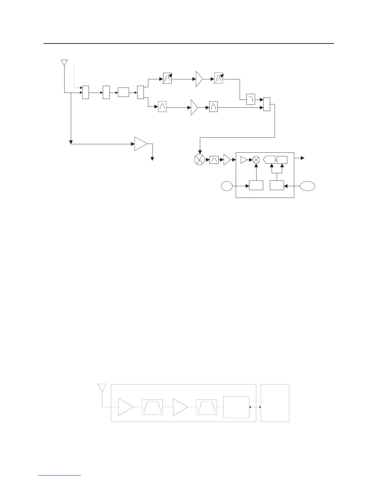
Figure 3-7. Receiver Block Diagram (UHF2 and VHF)
3.2.1.1 GPS
The GPS architecture employs a single chip GPS receiver which decodes GPS signals at
1575.42 MHz. It is capable of producing a final position solution including full tracking and data
decode capability. The GPS receiver will operate in the autonomous mode only.
The GPS signal is tapped at the antenna port via a series resonant network which provides a very
low capacitive load to the transceiver. The signal is routed though a GPS LNA and it's output is
applied to the RF-Controller interface connector where it is eventually routed to the expansion board
for processing by the GPS IC.
The GPS receiver is setup in an autonomous one track always (OTA) mode, also known as
continuous navigation. This means the GPS will continuously track satellites for as long as the radio
is powered to ensure the best possible accuracy. In the event the radio loses visibility of the satellites
due to terrain or environmental factors such as driving through a tunnel or entering a building, the
GPS will temporarily lose its position fix. A power savings algorithm will then cycle the GPS in and
out of a sleep mode at approximately 90 second intervals until the radio has moved back into an
environment where GPS signals are present.
The user will be able to view the current latitude, longitude, and time/date stamp on the radio’s
display. The radio can also be configured to send its’ location to the system at predetermined
intervals (LRRP). Depending on system options, the user may be able to enable/disable the GPS
receiver.
Figure 3-8. GPS Diagram
SW
2:1
VHF
UHF2
Abacus III
2nd
LO
18Mhz
CLK
CLK
Dec.
Filter
LO
ADC
ΣΔ
SW
2:1
PER
SP3T
AUX
DPLXR
To
RF/Vocon
Connector
SSI
RMT Port
GPS IC
GPS Receiver Circuit
ntenna
OMAP
Processor

 Loading...


