Basic Theory of Operation: Analog Mode of Operation Sec 1: 3-7
3.2.1.6 Analog To Digital Converter
The ADC IC's front end down converts the first IF to a second IF, a 2.25 MHz signal. The second IF
is sampled at 18 MHz, a signal generated by an integrated clock synthesizer. The sampled signal is
decimated by a factor of 900 to 20 kHz and converted to SSI format at the ADC's output. The Serial
Synchronous Interface (SSI) serial data waveform is composed of a 16 bit in-phase word (I) followed
by a 16 bit Quadrature word (Q). A 20 kHz Frame Synch and a 1.2 MHz clock waveform are used to
synchronize the SSI IQ data transfer to the Digital Signal Processor IC (OMAP) for post-processing
and demodulation.
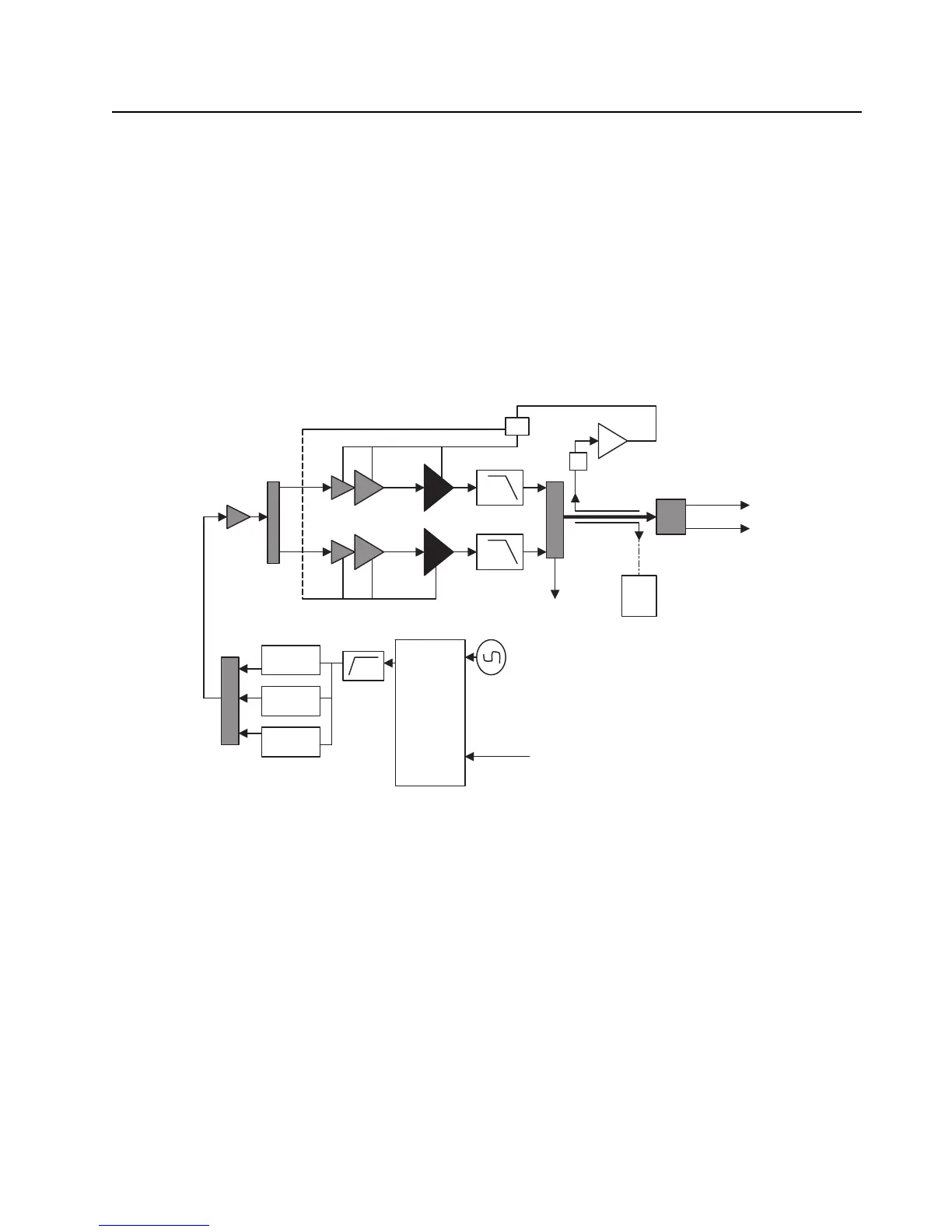
3.2.2 Transmitting
When the radio is transmitting, microphone audio is digitized and then processed by the DSP and
sent to the Trident IC (see Figure 3-9 to Figure 3-13) via the SSI interface. The Trident IC processes
the SSI data for application to the voltage controlled oscillator as a modulation signal.
Figure 3-9. Transceiver (VHF and 700–800 MHz) Block Diagram
To Antenna
To RMT Port
To RX
Log amp Power Detector
Digital RF Attenuator
FET 700/800
Driver Amplifier
FET VHF
VCO Module
VCO Module
VCO Module
Trident IC
SP3T RF Switch
Switch
TX SSI from Vocon
TX Buffer Amp
RF Switch
Harmonic Filters
Loop Filter
Ref. Oscillator
Coupler
Rev Power Detection
RF Switch Matrix
SP2T RF Switch

 Loading...


