Sec 2: 8-18 Disassembly/Reassembly Procedures: Serviceable Components of the Main Sub-Assemblies
8.8 Serviceable Components of the Main Sub-Assemblies
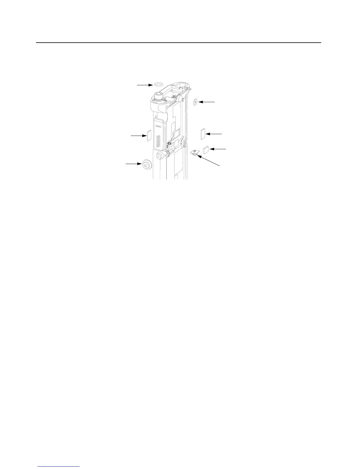
8.8.1 Servicing Main Chassis Assembly (K)
Figure 8-26. Serviceable Components – Main Chassis Assembly
8.8.1.1 Servicing Chassis Pads:
1. Complete steps from Section 8.7.1. through Section 8.7.9. of Section “8.7 Radio
Disassembly” on page 2:8-11.
2. Carefully peel off the pad(s) that need replacing (i.e. VOCON Pad (9),
Expansion Board Pad (9) and/or Coin Cell Pad (8) from the chassis.
3. Use the Black Stick to help remove any difficult sections of the pad(s).
4. Clean the area once the pad(s) are removed to ensure it is free of adhesive and debris.
5. Peel the liner off the new pad(s) and place in the respective location.
6. Apply slight pressure to set the adhesive.
8.8.1.2 Servicing Chassis Screw Boss Cap:
1. Complete steps from Section 8.7.1. through Section 8.7.4. of Section “8.7 Radio
Disassembly” on page 2:8-11.
2. Carefully pry off the Universal Connector Cover (38) with the Black Stick from the
Main Chassis Assembly (4) as shown in Figure 8-26.
3. Press the new Cap down onto the boss until it is fully seated.
NOTE: There should be no gap between the chassis boss top face and the corresponding
interior surface of the cap.
8.8.1.3 Servicing Antenna O-ring:
1. Complete steps from Section 8.7.1. through Section 8.7.9. of Section “8.7 Radio
Disassembly” on page 2:8-11.
2. Remove the O-ring (6) with the Black Stick.
3. Reinstall the O-ring by rolling it over the threaded portion of the antenna hub until it sets in its
groove.
NOTE: Ensure the O-ring is not twisted.
Microphone Seal (19)
Thermal Pad (9)
Thermal Pad (9)
Coin Cell Pad (8)
Chassis Ground Contact (7)
Universal Connector Cap (29)
O Ring (6)

 Loading...


