Disassembly/Reassembly Procedures: Radio Disassembly Sec 2: 8-17
2. With a pair of pliers, grasp the Frequency Knob and pull it upward, until it is free from its shaft.
B. Remove the Volume Knob
To remove the Volume Knob (12):
1. Hold the radio in one hand so that the top of the radio faces upward and the front of the radio
faces you.
2. With a pair of pliers, grasp the Volume Knob and pull it upward.
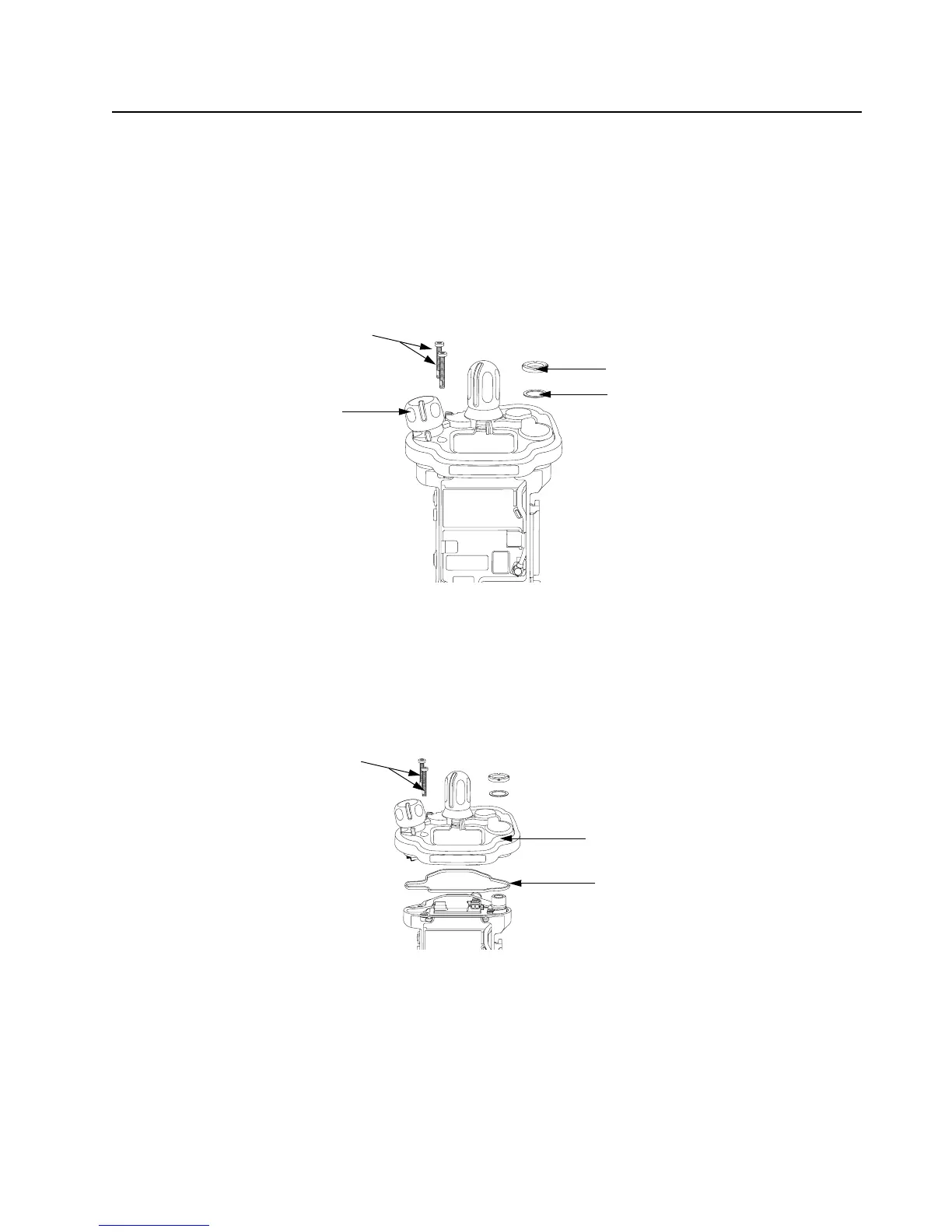
Figure 8-24. Remove Knobs and Fastener Hardware
8.7.9 Removal of the Control Top Assembly (J)
i. Use a Torx Plus IP8 bit to remove the two Control Top Screws (26). See Figure 8-25.
NOTE: Ensure the Control Top flex is disconnected from the VOCON Board (G) to prevent
damage to the flex or connector.
Figure 8-25. Remove Control Top Assembly
II. Gently separate the Control Top Assembly (J) from the Main Chassis Assembly (K).
NOTE: Place the Control Top Assembly (J) and the remaining Main Chassis Assembly (K)
on an ESD safe surface free from debris.
Antenna Spanner Nut (16)
Antenna Washer (15)
Control Top Screws (26)
Volume Knob (12)
Control Top Assembly (J)
Control Top Screws (26)
Control Top Seal (14)

 Loading...


