Sec 2: 3-10 Basic Theory of Operation: Controller Section
3.4 Controller Section
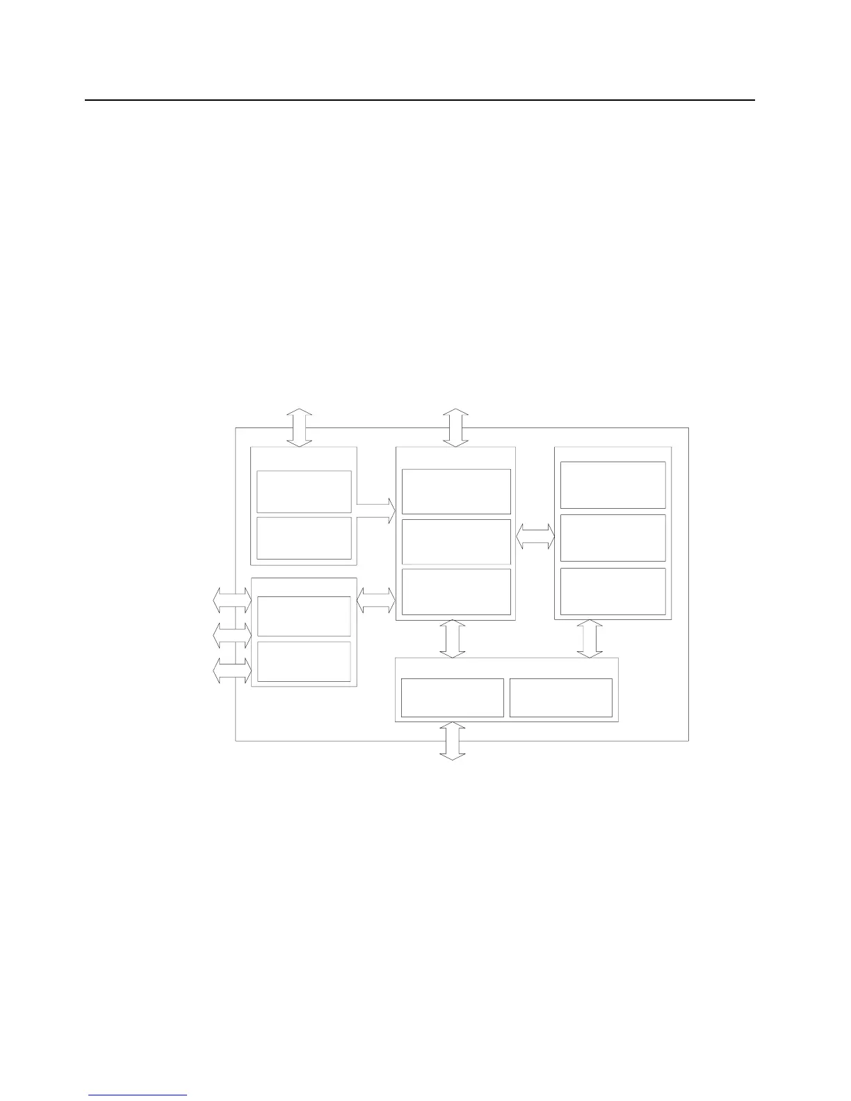
The controller section (see Figure 3-13) comprises of five functional sections that are split among
three boards, which are the VOCON, EXPANSION and OPTION boards. The main functional section
consists of a dual core ARM and DSP controller, an encryption processor (MACE), Flash memory,
and a Double Data Rate Synchronous Dynamic Random Access Memory (DDR SDRAM). The
Power and Clocks section includes a power management IC (MAKO) and various external switching
regulators, and two clock sources (12 Mhz and 24.576 Mhz) from which all other controller digital
clocks are derived. The Audio section has a CODEC and a class-D audio power amplifier that
provides the radio with a multiple microphone, multiple speaker design. The User Interface section
provides communication and control to the top and main Liquid Crystal Displays (LCD) on the radio,
as well as a keypad and a side connector interface conforming to Universal Connector
specifications. The Expansion Memory, GPS and Option section comprises of a Micro SD memory
interface, Global Positioning Satellite (GPS) processor, and an Option Board for radio feature
upgrades.
Figure 3-13. Controller Block Diagram
The ARM controller core of the OMAP processor handles the power up sequence of all devices,
including firmware upgrades, and all operating system tasks that are associated with FLASH and
SDRAM memories and user interface communication. The FLASH memory (64 MB) is required to
store the firmware, tuning, and Codeplug settings, which upon initialization get read and stored into
SDRAM (32 MB) for execution. The ARM and DSP core jointly control and configure audio, wireless
and RF devices linked to the Serial Peripheral Interface (SPI) and Synchronous Serial Interface
(SSI) buses to enable radio FM and optional wireless communication protocols. For encryption, a
separate ARM processor is used (MACE) to encode and decode encryption packets coming in from
the main OMAP processor through the SSI interface. Its firmware is flashed via the main processor
during an upgrade request to its internal FLASH memory.
USER INTERFACE
Top Display
Data Display
KeyPad
Expansion Board:
Side Connector
POWER & CLOCKS
Clocks Sources:
12 Mhz
24.576 Mhz
CONTROLLERS & MEMORY
ARM Processor
Digital Signal Processor
Flash Memory
DDR Memory
Encryption Processor
EXPANSION MEMORY, GPS & OPTIONS
Option Board
Expansion Board:
SD Card
GPS
Voltage Regulators
AUDIO
Expansion Board Audio:
Main Amplifier / Speaker
Main Microphone
Data Speaker
Data Microphone
Acc. Speaker
Acc. Microphone
Micro SD
Interface
RF Interface
Battery Supply
Top Display
Interface
Data Display &
KeyPad
Side
Connector

 Loading...


