Disassembly/Reassembly Procedures: Serviceable Components of the Main Sub-Assemblies Sec 1: 8-23
8.8.3 Servicing Knobs and Top Bezel Assembly (H)
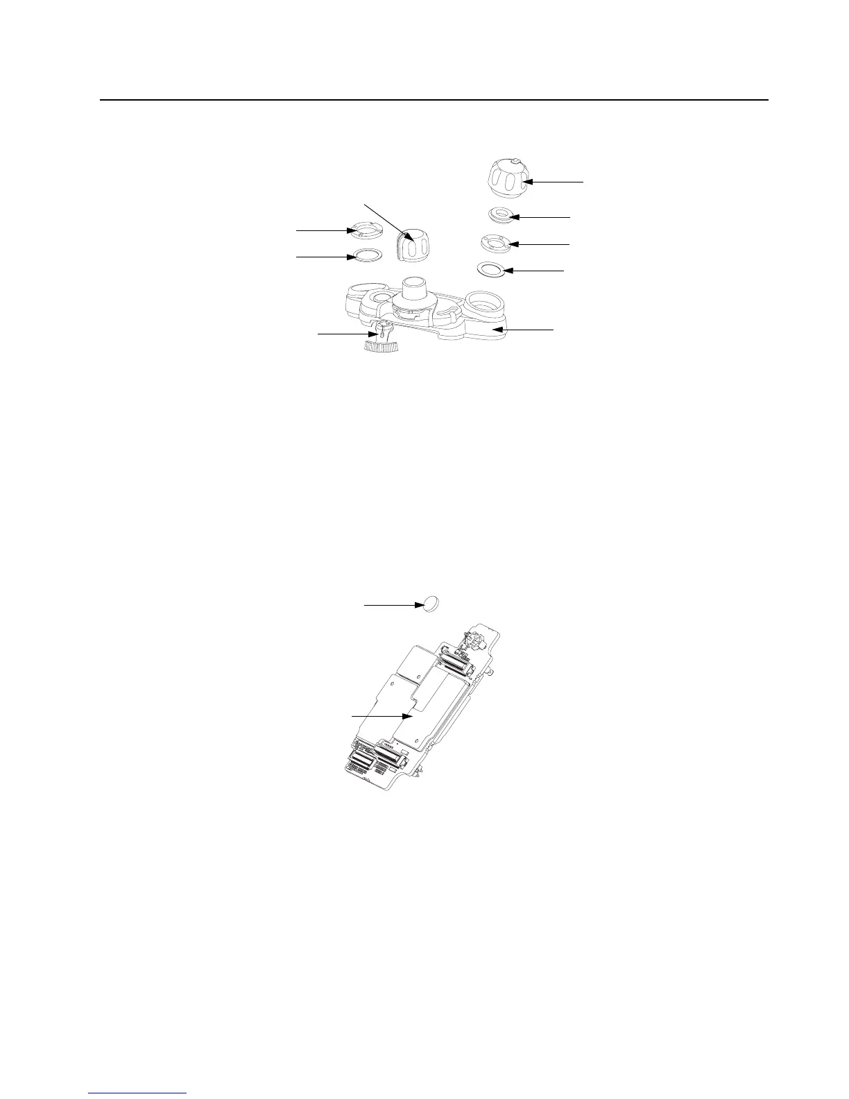
Figure 8-31. Top Bezel Assembly
8.8.3.1 Secure Lever
1. Complete steps from Section 8.7.8. of Section “8.7 Radio Disassembly” on page 1:8-12.
2. Pull the Secure Lever (14) straight out of Control Top Bezel Assembly (11) as shown in
Figure 8-31.
3. Insert the lever's arm into the bezel's slot.
NOTE: All serviceable components on the Top Bezel Assembly are shown in Figure 8-31.
8.8.4 Servicing VOCON Board Assembly (G, N)
Figure 8-32. VOCON Board Assembly
8.8.4.1 Back up Battery
1. Complete steps from Section 8.7.1. through Section 8.7.7. of Section “8.7 Radio
Disassembly” on page 1:8-12.
2. Remove the battery with the Black Stick.
NOTE: Make sure the positive side is facing upwards.
3. Press the new battery into the battery carrier until it is secured and fully snapped into place.
NOTE: There are no other serviceable components on the VOCON Board Assembly.
Volume Knob (12)
Torque Adder (15)
Volume Spanner Nut (17)
Frequency Knob (13)
Antenna Spanner Nut (19)
Antenna Washer (18)
Volume Washer (16)
Secure Lever (14)
Control Top Bezel Assembly (11)
Battery (37)
VOCON Board

 Loading...


