Disassembly/Reassembly Procedures: Radio Reassembly Sec 2: 8-25
8.9 Radio Reassembly
This section contains instructions for reassembling the radio.
8.9.1 Reassemble the Main Sub Assemblies
8.9.1.1 Assemble Top Control Assembly (J) to Main Chassis Assembly (K)
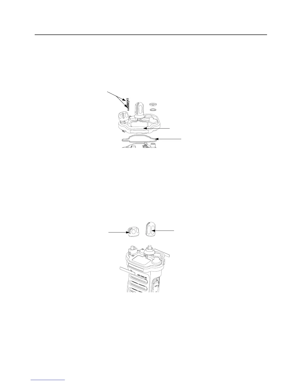
Figure 8-36. Control Top Bezel Assembly
1. Verify there are no surface irregularities such as scratches or indentations on both the Control
Top Main Seal Grove and the Seal's mating surface on the Main Chassis
Assembly (4). Also ensure that the Control Top Seal (14) and surrounding surfaces are free
of debris and other foreign material.
2. Verify Control Top Seal is properly seated into its groove and place Control Top Assembly
onto Main Chassis Assembly as shown in Figure 8-36.
3. Torque both screws with a Torx IP8 Bit and a torque Driver to 8 in-lbs.
8.9.1.2 Assemble Frequency and Volume Knobs Assembly (H)
Figure 8-37. Knobs Assembly
1. Align the D-shaped part of the Volume Shaft with the D-shape hole in the Volume Knob and
press the Volume Knob (12) into place.
Control Top Assembly (10)
Control Top Screws (26)
Control Top Seal (14)
Frequency Knob (13)
Volume Knob (12)

 Loading...


