Chapter 3 Basic Theory of Operation
This chapter discusses the basic operational theory of the ASTRO APX 7000XE radio, which is a
wideband, synthesized radio available in the VHF (136–174 MHz), UHF1 (380–470 MHz),
UHF2 (450–520 MHz), 764 to 870 MHz, VHF/764 to 870 MHz, UHF1/764 to 870 MHz and VHF/
UHF1, UHF2/764 to 870 MHz and VHF/UHF2, frequency bands.
All ASTRO APX 7000XE radios are capable of both analog operation (12.5 kHz or 25 kHz
bandwidths), ASTRO mode (digital) operation (12.5 kHz only) and X2-TDMA mode (25 kHz only).
3.1 Major Assemblies
The ASTRO APX 7000XE radio includes the following major assemblies (see Figure 3-1):
• VOCON Board – contains a dual-core processor which includes both the microcontroller unit
(MCU) and a digital signal processor (DSP) core, the processor's memory devices, an audio
and power supply support integrated circuit (IC), a digital support IC, external audio power
amplifier, and Type III secure IC.
• Transceiver (XCVR) Board – contains all transmit, receive, and frequency generation circuitry,
including the digital receiver back-end IC and the reference oscillator.
• Expander Board – contains the internal audio power amplifier circuitry and the Global
Positioning System (GPS) IC and support circuitry.
• Option Board – capability for future expansion for additional features and functionality.
• Top Display – 112 pixels x 32 pixels, transflective monochrome liquid crystal display (LCD).
• Control Top – contains five switches: On/Off & Volume Knob, a 16 position Channel/
Frequency Knob with concentric 2 position switch (for Secure Enable/Disable operation), a 3
position toggle switch for Zone Selection, and a push button switch used for Emergency calling.
The control top also includes an TX/RX LED that is solid amber upon receive, red on PTT, and
blinks amber on secure TX/RX.
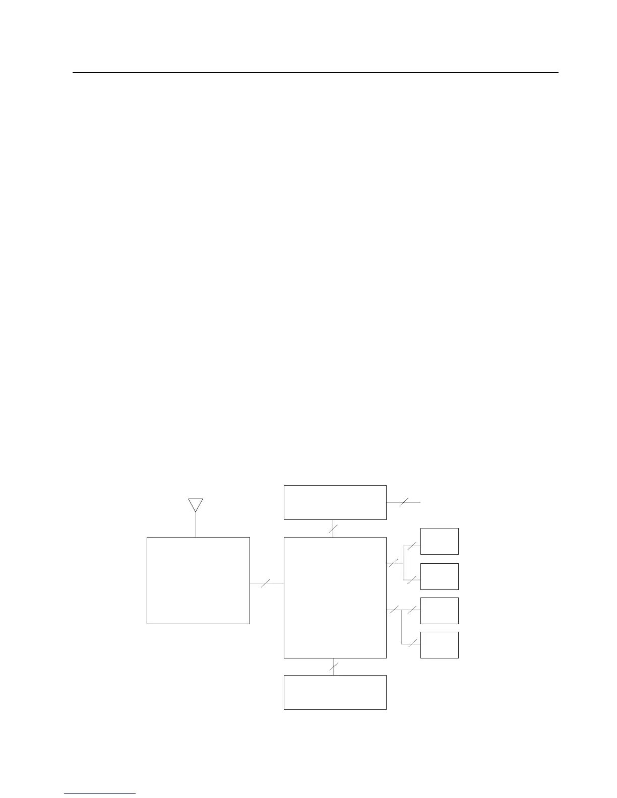
Figure 3-1. APX 7000XE Overall Block Diagram (VOCON Board MNCN6203)
Expander
External accessory connector
Board
External antenna
Front display
Transceiver VoCon
Keypad
Board Board
Top display
Controls top
Option
Board
40
60
14
80
50
30
50 20
30
60
Antenna

 Loading...


