EasyManuals Logo

Motorola APX 7000 Basic Service Manual

Motorola APX 7000
292 pages
To Next Page IconTo Next Page
To Previous Page IconTo Previous Page
Page #110 background imageLoading...
Page #110 background image
Sec 1: 8-22 Disassembly/Reassembly Procedures: Serviceable Components of the Main Sub-Assemblies
Figure 8-29. Remove Chassis Ground Contact
NOTE: There are no other serviceable components on the Main Chassis Assembly (K).
8.8.2 Servicing Control Top Assembly (J)
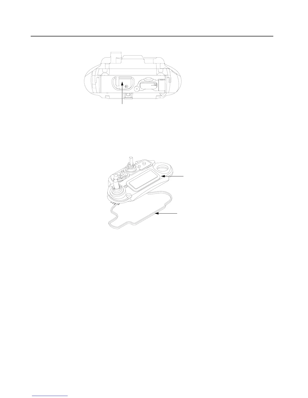
Figure 8-30. Control Top Assembly and Control Top Seal
8.8.2.1 Control Top Main Seal
1. Complete steps from Section 8.7.1. through Section 8.7.9. of Section “8.7 Radio
Disassembly” on page 1:8-12.
2. Remove the Control Top Seal (10) with the Black Stick.
3. Replace the new seal into the groove provided in the Control Top Assembly's casting.
4. Ensure that seal is set properly and not stretched.
NOTE: There are no other serviceable components on the Control Top Assembly (J).
Chassis Ground Contact (6)
Control Top Seal (10)
Control Top Assembly (9)

Table of Contents

Other manuals for Motorola APX 7000

Questions and Answers:

Question and Answer IconNeed help?

Do you have a question about the Motorola APX 7000 and is the answer not in the manual?

Motorola APX 7000 Specifications

General IconGeneral
Digital TechnologyP25 Phase 1 and Phase 2
Emergency ButtonYes
Frequency Range136-174 MHz (VHF), 380-470 MHz (UHF Range 1), 450-520 MHz (UHF Range 2), 764-870 MHz (700/800 MHz)
DisplayColor LCD
EncryptionAES, DES
Water ResistanceIP67
GPSYes
BluetoothYes
Operating Temperature-30°C to +60°C
Weight391 g (with standard battery)

Related product manuals