Sec 2: 8-16 Disassembly/Reassembly Procedures: Radio Disassembly
Figure 8-22. Remove RF Board Assembly
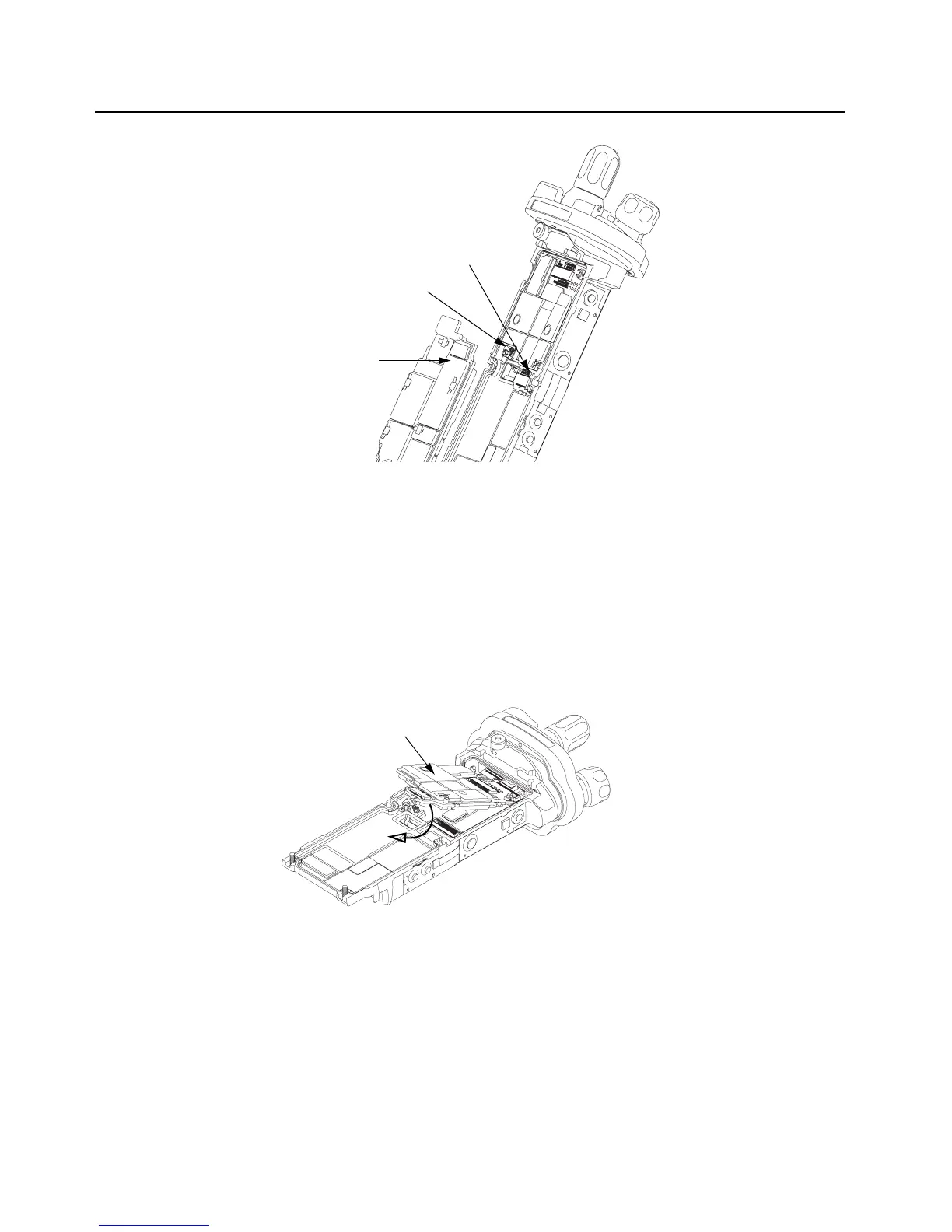
8.7.7 Removal of the VOCON Board Assembly (G)
NOTE: Reconfirm the Flex connector between the Control Top Assembly (J) and the
VOCON Board Assembly (G) or, if so equipped, the Option Board is disconnected
(see step 2 on page 2:8-30). Failure to do so may damage the connectors or the
flex.
1. Gently rotate the VOCON Board Assembly just enough to clear the Main Chassis and Option
Board connector. Slide out the VOCON Board Assembly as shown in Figure 8-23.
Figure 8-23. Remove VOCON Board Assembly
8.7.8 Removal of the Knobs
A. Remove the Frequency Knob
To remove the Frequency Knob (13):
1. Hold the radio in one hand so that the top of the radio faces upward, and the front of the radio
faces you.
Connector
RF Board Assembly (32)
Small Coax Cable
VOCON Board Assembly (G)

 Loading...


