Disassembly/Reassembly Procedures: Serviceable Components of the Main Sub-Assemblies Sec 2: 8-19
8.8.1.4 Servicing Microphone Membrane
1. Complete steps from Section 8.7.1. through Section 8.7.4. of Section “8.7 Radio
Disassembly” on page 2:8-11.
2. Carefully peel off the Microphone Membrane (19) from the Main Chassis Assembly (4).
3. Clean the area, once the Microphone Membrane is removed, to ensure it is free of adhesive
and debris. Ensure nothing comes in contact with the microphone while cleaning.
4. Remove the backer from the Microphone Membrane.
5. Carefully place the Microphone Membrane centered on the top surface of the microphone
boss area on the Main Chassis. Ensure the membrane is flat with no ripples or folds. Press
down firmly, applying 2-3 lbs. of force.
8.8.1.5 Servicing Chassis Ground Contact:
NOTE: Chassis Ground Contact (7) will be damaged during disassembly.
1. Complete steps from Section 8.7.1. through Section 8.7.9. of Section “8.7 Radio
Disassembly” on page 2:8-11.
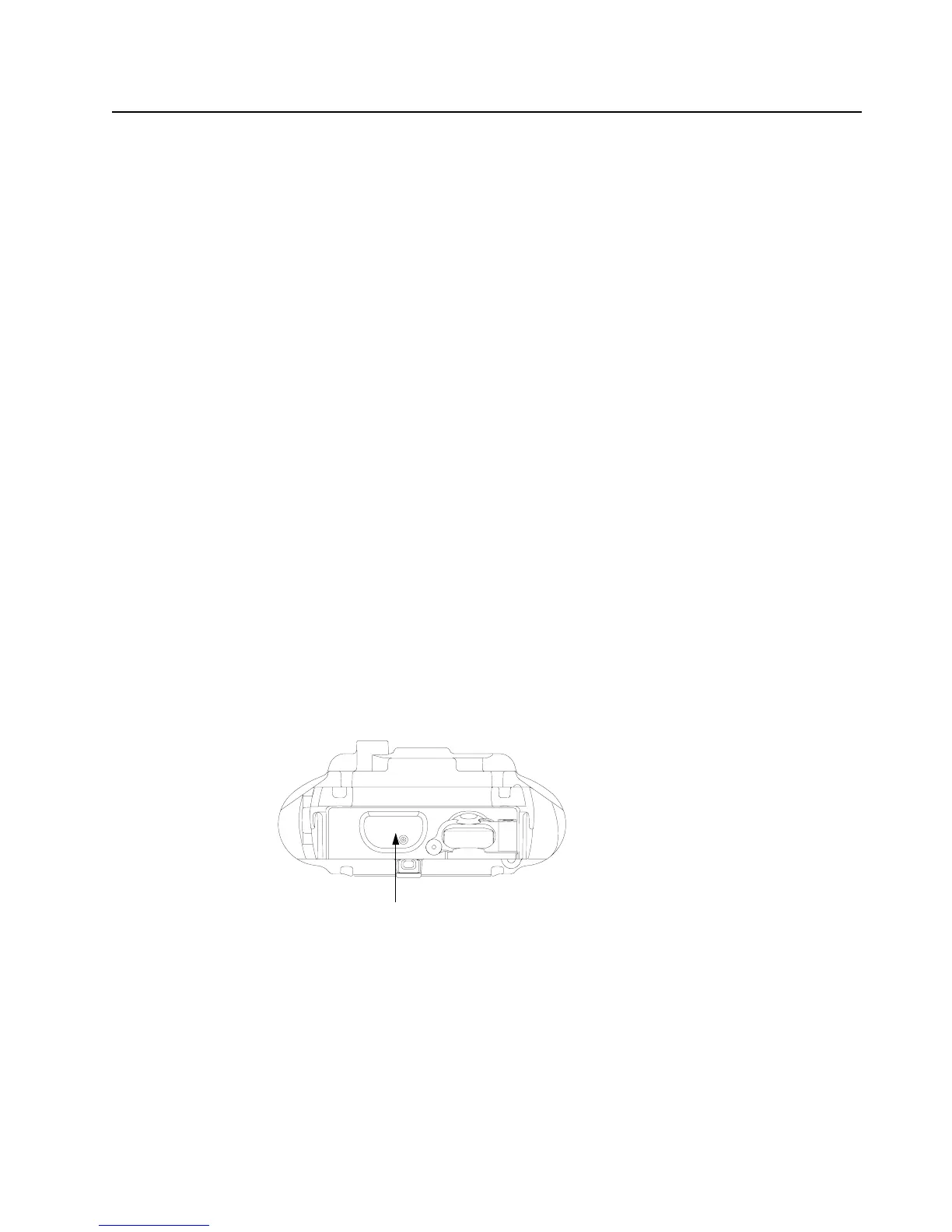
2. Slide the Black Stick under the Chassis Ground Contact (7) through the opening on the RF/
VOCON PCB side of the radio to lift off the contact.
3. Clean the area once the Chassis Ground Contact is removed to ensure it is free of adhesive
and debris.
4. Remove the backer of the Chassis Ground Contact and place it in the appropriate location
with a pair of flat tip tweezers by aligning the hole in the Ground Contact with the post located
on the chassis. Ensure the Ground Contact is centered in the opening and the outer surface
of the Ground Contact is parallel to the area adjacent to it in the chassis as shown in
Figure 8-27.
5. Apply pressure to the adhesive to activate it.
Figure 8-27. Remove Chassis Ground Contact
NOTE: There are no other serviceable components on the Main Chassis Assembly (K).
Chassis Ground Contact (7)

 Loading...


