Sec 2: 8-20 Disassembly/Reassembly Procedures: Serviceable Components of the Main Sub-Assemblies
8.8.2 Servicing Control Top Assembly (J)
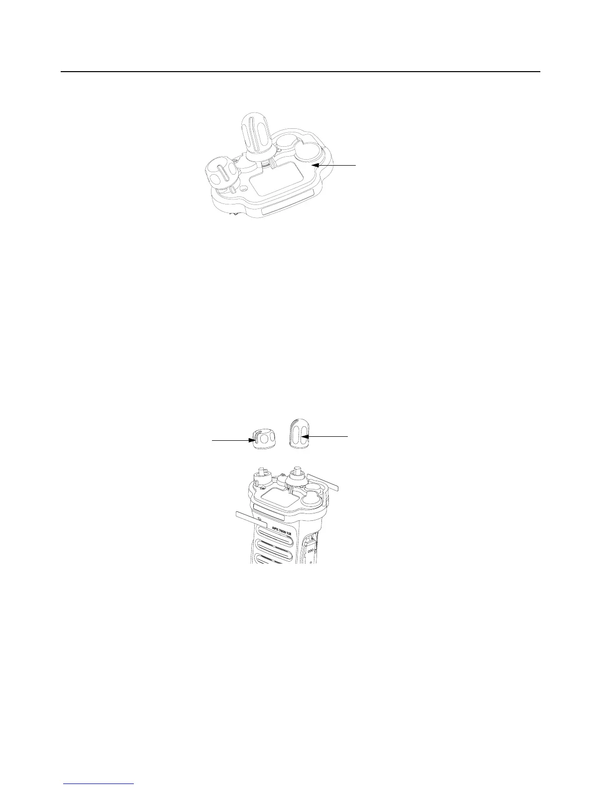
Figure 8-28. Control Top Assembly and Control Top Seal
8.8.2.1 Control Top Main Seal
1. Complete steps from Section 8.7.1. through Section 8.7.9. of Section “8.7 Radio
Disassembly” on page 2:8-11.
2. Remove the Control Top Seal (14) with the Black Stick.
3. Replace the new seal into the groove provided in the Control Top Assembly's casting.
4. Ensure that seal is set properly and not stretched.
NOTE: There are no other serviceable components on the Control Top Assembly (J).
8.8.3 Servicing Knobs and Top Bezel Assembly (H)
Figure 8-29. Frequency and Volume Knobs Assembly
Knobs should be removed when damaged. To remove knobs:
• Firmly hold the radio in one hand and use a pair of pliers to grib the knob.
NOTE: The knobs are designed to be difficult to remove, however, it will come off. If the
metal D clip sticks to the knob post, remove the D clip prior to putting on the new
knob.
Control Top Assembly (10)
Frequency Knob (13)
Volume Knob (12)

 Loading...


