Disassembly/Reassembly Procedures: Serviceable Components of the Main Sub-Assemblies Sec 2: 8-21
8.8.4 Servicing VOCON Board Assembly (G)
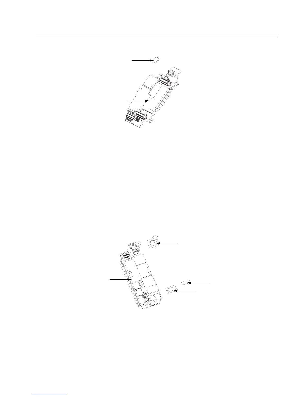
Figure 8-30. VOCON Board Assembly
8.8.4.1 Back up Battery
1. Complete steps from Section 8.7.1. through Section 8.7.7. of Section “8.7 Radio
Disassembly” on page 2:8-11.
2. Remove the battery with the Black Stick.
NOTE: Make sure the positive side is facing upwards.
3. Press the new battery into the battery carrier until it is secured and fully snapped into place.
NOTE: There are no other serviceable components on the VOCON Board Assembly.
8.8.5 Servicing of RF Board Assembly
Complete steps 8.7.1 through 8.7.6 of Section “8.7 Radio Disassembly” on page 2:8-11.
Figure 8-31. RF Board Assembly
8.8.5.1 Battery Seal
1. Slide the Battery Connector Seal (35) from the battery contact header with the Black Stick.
2. Use the Black Stick and push the new Battery Connector Seal until it is properly seated onto
the RF Board surface.
Battery (31)
VOCON Board
Battery Connector Seal (35)
RF Board Assembly (F)
Outer Thermal Pad (33)
Inner Thermal Pad (34)

 Loading...


