EasyManuals Logo

Motorola APX 7000 Basic Service Manual

Motorola APX 7000
292 pages
To Next Page IconTo Next Page
To Previous Page IconTo Previous Page
Page #121 background imageLoading...
Page #121 background image
Disassembly/Reassembly Procedures: Radio Reassembly Sec 1: 8-33
Figure 8-44. Insert VOCON Board
8.9.1.4 Assemble RF Board Assembly (F)
1. Inspect the Battery Connector Seal (41) on the RF Board Assembly (F) for any damage or
debris. Replace seal if necessary.
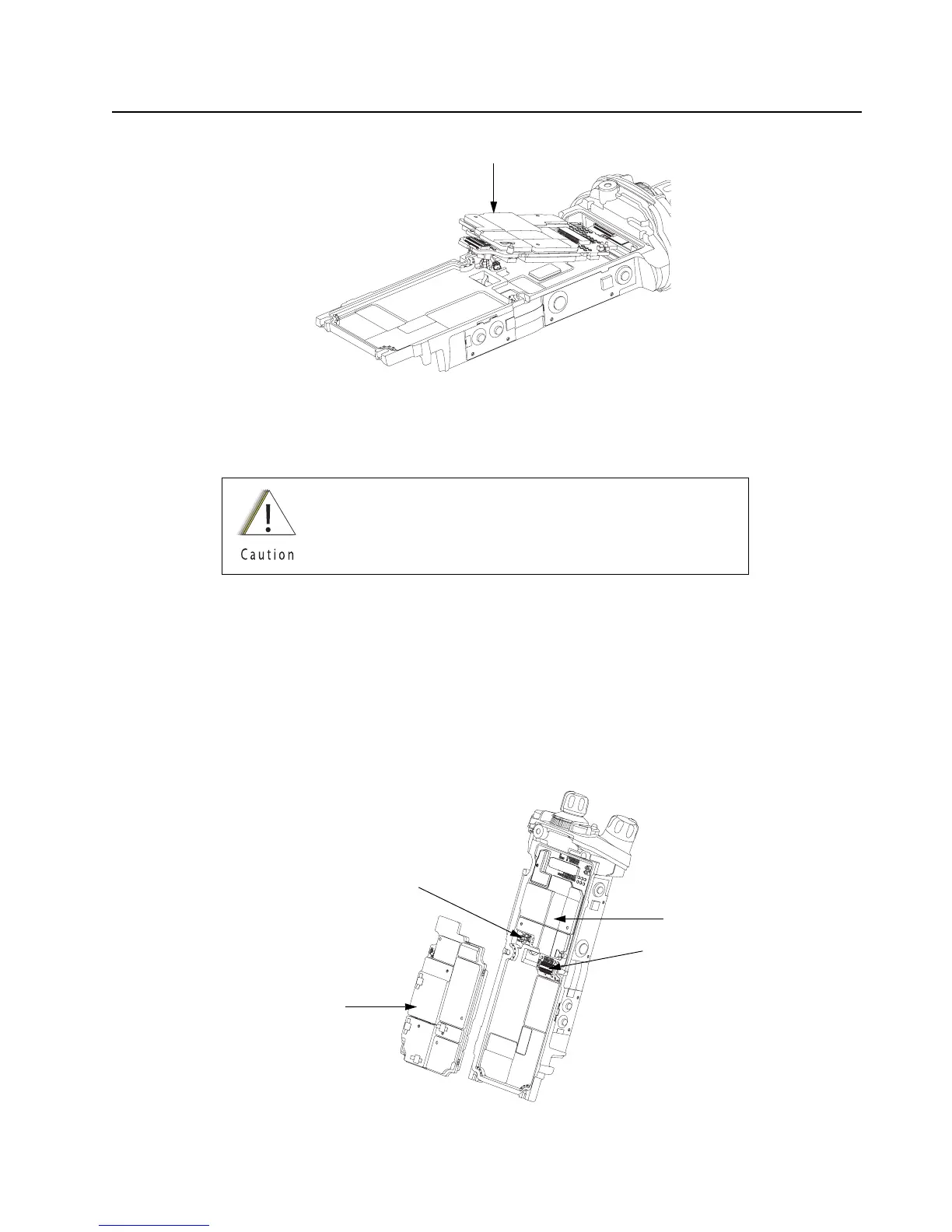
2. Connect the small coaxial cable connector into the RF Board (38).
3. Connect the RF Board (38) to the VOCON Board as shown in Figure 8-45.
NOTE: Do not connect the Antenna coax at this time. Front Housing Assembly (1) must be
snapped in place prior to connecting the coax.
Figure 8-45. Connect RF Board to VOCON Board
Always replace with new thermal pads. See Section “8.8.5.2
Thermal Pads” on page 1:8-24.
VOCON Board Assembly (G, N)
Connector
RF Board Assembly (F)
Small Coax Cable
VOCON Board

Table of Contents

Other manuals for Motorola APX 7000

Questions and Answers:

Question and Answer IconNeed help?

Do you have a question about the Motorola APX 7000 and is the answer not in the manual?

Motorola APX 7000 Specifications

General IconGeneral
Digital TechnologyP25 Phase 1 and Phase 2
Emergency ButtonYes
Frequency Range136-174 MHz (VHF), 380-470 MHz (UHF Range 1), 450-520 MHz (UHF Range 2), 764-870 MHz (700/800 MHz)
DisplayColor LCD
EncryptionAES, DES
Water ResistanceIP67
GPSYes
BluetoothYes
Operating Temperature-30°C to +60°C
Weight391 g (with standard battery)

Related product manuals