MSENSE
®
DGA 9 7045899/02 EN – 11.2020 Page 104
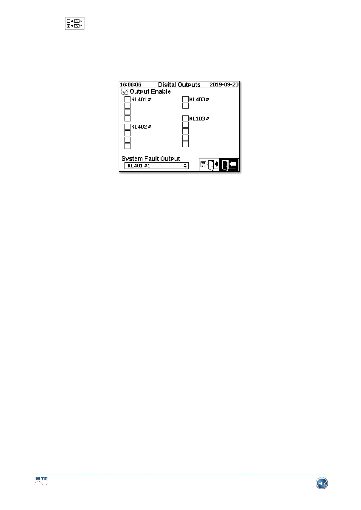
6.10.4.2 Test digital outputs
In order to test the outputs and their peripherals, the alarm outputs in this menu can be set manually.
Use the arrow keys to select the desired output and then the input key to switch the output on and off.
The ten relay outputs are labelled with KL401 #, KL402 # and KL403 # (see chapter 5.3) [5] - X401: 1
... 8, [6] - X402:1 ... 8 and [7] - X403:1 ... 4).
5 optional optocouplers outputs are labelled KL103 # (see chapter 5.3) [18] - X103:1 ... 10)
6.10.4.2.1 System fault – Output
The MSENSE® DGA 9 boasts a system monitoring function, which can be issued via a digital output.
The following internal sources of fault are monitored:
• Loss of time
• Data storage not ready
• RTC not ready for operation (buffer capacitor empty)
The system fault can be individually adjusted to one of the 15 digital outputs (standard: relay output 1).
The selection can be made in the field system fault output:
• KL401 #1 X401:1&2 (Relay output 1)
• KL401 #2 X401:3&4 (Relay output 2)
• KL401 #3 X401:5&6 (Relay output 3)
• KL401 #4 X401:7&8 (Relay output 4)
• KL402 #1 X402:1&2 (Relay output 5)
• KL402 #2 X402:3&4 (Relay output 6)
• KL402 #3 X402:5&6 (Relay output 7)
• KL402 #4 X402:7&8 (Relay output 8)
• KL403 #1 X403:1&2 (Relay output 9)
• KL403 #2 X403:3&4 (Relay output 10)
• KL103 #1 X10³:1&2 (Optical coupler output 1 optional)
• KL103 #2 X10³:3&4 (Optical coupler output 2 optional)
• KL103 #3 X10³:5&6 (Optical coupler output 3 optional)
• KL103 #4 X10³:7&8 (Optical coupler output 4 optional)
• KL103 #5 X10³:9&10 (Optical coupler output 5 optional)
• - (no assignment of the system fault to an output)
If the output has already been allocated an alarm, the terminal number is displayed with an exclamation
mark (e.g.: ! KL401 #1).
When in fault-free status (during the device’s operation), the relay contact is closed or the optocoupler
is connected through.
 Loading...