MSENSE
®
DGA 9 7045899/02 EN – 11.2020 Page 21
Installation
Once installation preparations have been completed, the MSENSE® DGA 9 can be installed. Installa-
tion is divided into 3 steps:
• Mechanical installation [4.4.1]
• Electrical connection [4.4.2]
• Initial start-up (4.4.3)
4.4.1 Mechanical installation
The sequence for mechanical installation depends on the connection on the transformer side. There
are 2 basic types of mechanical installation:
• Direct mounting [4.4.1.1]
• Indirect mounting [4.4.1.2]
Remark: In the event of heavy vibrations at the installation valve/gate valve, strain should be relieved
using a support.
4.4.1.1 Direct mounting
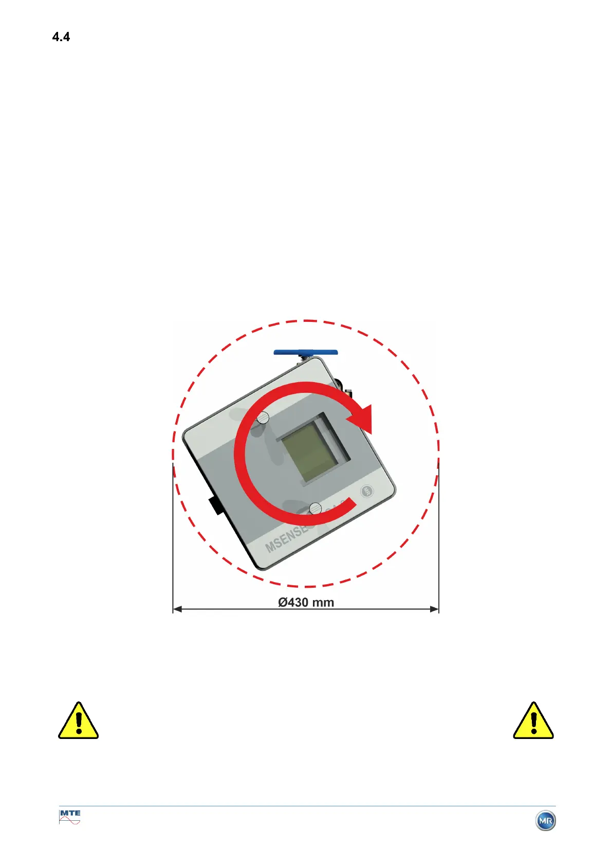
In the case of direct mounting, the MSENSE® DGA 9 is screwed directly to the threaded flange, i.e.
the device is turned around its own axis in order to be fixed in place. This type of installation requires
free space measuring 430 mm in diameter around the centre of the connecting flange.
The threaded joint can be sealed and fixed in place using thread sealing tape or thread adhesive.
• Direct mounting with thread sealing tape [0]
• Direct mounting with thread adhesive [4.4.1.1.2]
Note !!!
Do not remove the protective cap (by turning it slowly) until
you are ready to install the MSENSE
®
DGA 9
at the connecting valve/gate valve!


 To Next Page