MSENSE
®
DGA 9 7045899/02 EN – 11.2020 Page 58
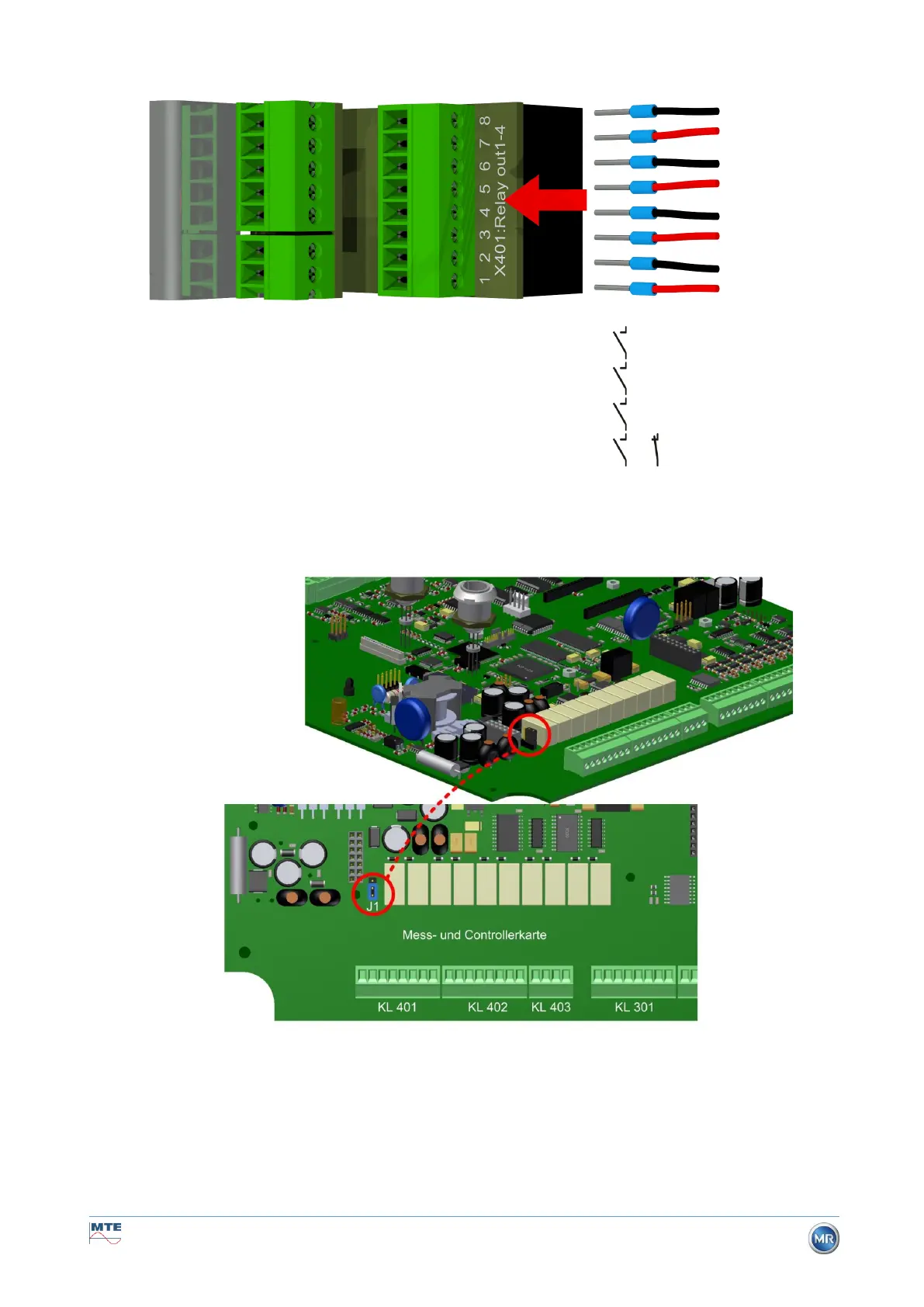
Connection terminals X401: Relay outputs 1 ... 4 [4 x Relay-out X401]
Connection for relay outputs 1 ... 4 (220 VDC/VAC / 2 A / 60 W)
X401:8 DOR4 Relay output 4
X401:7 DOR4 Relay output 4
X401:6 DOR3 Relay output 3
X401:5 DOR3 Relay output 3
X401:4 DOR2 Relay output 2
X401:3 DOR2 Relay output 2
X401:2 DOR1 Relay output 1
X401:1 DOR1 Relay output 1
Relay contacts
or (J1: see also 5.3.1)
5.3.1 Configuration of relay output 1 with coding bridge 1 (J1)
If coding bridge 1 is inserted as shown in the following figure, relay output 1 is configured so
that the contact is closed during the device’s operation. In the event of a fault, the contact
opens.
Coding bridge 1 for configuring relay contact 1 (X401 / KL401)
Relays
Output 4
Relays
Output 3
Relays
Output 2
Relays
Output 1