Installation
GALAXY GX2
19
US
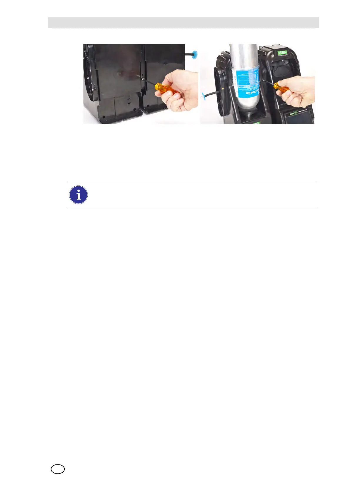
(4) If connecting multiple Test Stands, remove the white gas plugs [ Fig. 3] from all units ex-
cept the farthest right Test Stand. If using ammonia or chlorine test gas, read the restriction
found under chapter 2.8 “Special Conditions for Use with Reactive Gases” regarding the
white plugs.
(5) Continue adding Test Stands to the right and Cylinder Holders to the left [ Fig. 10].
3.2 Connect a Test Gas Source Without a Cylinder Holder
If high-pressure, high-capacity test gas cylinders ar
e preferred, an optional demand regulator
(p\n 710289) is available for cylinders with pressure less than (<) 3000 psi. Testing from an inde-
pendent gas source will require additional setup effort, as described in the Cylinder Configuration
section [ chapter 4.7].
(1) On the left-hand side of the Test Stand, ensure all five barb fittings are in place and straight-
ened.
(2) Place the user-supplied regulator onto the gas cylinder and secure a length of tubing onto its
outlet.
(3) Securely fit the end of the tubing over the appropriate barb fitting on the GALAXY GX2.
3.3 Network Test Stands
Test Stands that are banked together should be connected through the provided Ethernet cable.
The Master Test Stand is the one located on the furthest right of the bank.
(1) Insert the short Ethernet cable into the left side jack of each Test Stand (1) and connect it to
the right side jack of the neighboring unit (2) [ Fig. 11].
Z One interconnect Ethernet cable is included with each Test Stand.
When connecting two or more Test Stands ensure the white plugs are secured on the
right side of the farthest right unit to prevent gas leakage.