GALAXY GX2
10
Introduction
MSA
US
ware, and configuration options anticipate the user's needs and provide superb efficiency in this
next generation Automated Test System.
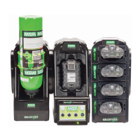
GALAXY GX2 System Features and Options
The GALAXY GX2 automatically identifies the type of gas detector inserted into the Test Stand.
Based on user-defined settings, the Test Stand then performs bump tests and/or calibrates the
instrument. The data collected from each test event is stored to a memory card [ chapter 2.2]
and/or optional MSA Link™ Pro software application for data analysis (refer to the MSA Link Pro
end-user manual).
2.1 Power Supply
The Test Stand supplies power to the attached ele
ctronic Cylinder Holders. The Test Stand and
Multi-Unit charger are powered individually by one of the following methods:
- Power Module: Input power requirements: 100 - 240 VAC, 47 - 63 Hz
(Several different prong types are available for world-wide AC sockets).
- Optional Vehicle Module 12/24 VDC (For use in a cigarette lighter socket).
2.2 The Test Stand
The Test Stand performs the following functions:
- Bump or calibration testing per user setup.
- Records test results to the optional memory card and to an optional networked PC interface.
- Sends gas detector Instrument Periodic and/or Session datalogs to a networked PC interface.
- Provides optional instrument charging capability.
- USB key allows gas detector settings to be changed securely, with the touch of the Test Stand
screen.
- Permits printing of test results to an instrument sticker or receipt, with the optional Receipt/
Sticker Printer.
- Sends e-mail notification of system alerts per user setup.
An LED indicator shows the status of the Test Stand:
- Green light indicates that the Test Stand hardware and software are fully functional.
- Blinking green light indicates that the Test Stand is performing the user specified test or data-
log download.
- Blinking yellow light indicates that the Test Stand is in error and cannot be used for gas detec-
tor testing. Diagnostic information is available as described on the "GX2 Status" screen on the
Test Stand and in the Troubleshooting section of this manual [ chapter 6].
- Red light indicates that the last calibration or bump test failed.
NOTICE
Use of a power supply not specified by MSA will void the instrument warranty and could cause
damage to the GALAXY GX2.
 Loading...