140
EN
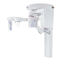
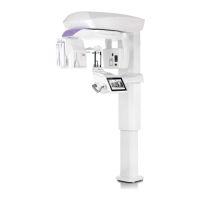
hyperion - TECHNICAL MANUAL
3.7.1 CONNECTOR LIST
CONNECTOR DESCRIPTION
J9 Main axis photocell
J5 Not used
J6 Not used
J4 Not used
J10 Auxiliaryphotocell
J15 Notusedinanyconguration
J7 Not used
J14 Main axis photocell
J11 48Vpowersupply
J1 CAN connector
J3 Not used
J2 CANconnector(AlternativetoJ1,usuallynotused)
J12 48Vauxilaryconnector(Notused)
3.7.2 Diagnostic LEDs
LED COLOUR DEFAULT STATUS FAULT STATUS DESCRIPTION
DL9(zeroA) Yellow X axis photocell (OFF if photo-
cellisfree,ONifsephotocellis
obscured or disconnected)
DL8(zeroB) Yellow Auxiliaryphotocell(OFFifpho-
tocellisfree,ONifsephotocell
is obscured or disconnected)
DL2 (5.0V) Green ON OFF 5Vpowersupply
DL3 (3.3V) Green ON OFF 3.3Vpowersupply
DL6 (CAN ACT) Yellow Blinking ON or OFF CAN communication
DL5(ERR) Red OFF ON Generic error
DL4 (CPU) Green Blinking ON o OFF CPUstatus, OFFduringstand-
by
DL9 (TOUCH) Green OFF NOT USED
DL7 (CAN 5.0V) Green ON OFF 5VCANpowersupply
3.7.3 Dip switches
DIP SWITCH NUM. DESCRIPTION NOTE
SW1 CAN termination AlwaysONforallthecongurations
1 2 3 4
CSENS 0 0 0 1
MSENS 0 0 1 0
SW2 Congurationmodality GSENS 0 0 1 1