AVIOR-24S ™
System Designer Reference Manual
NAVIOR-24S ™ Revision V1.00 20.05.2008
Figure Index
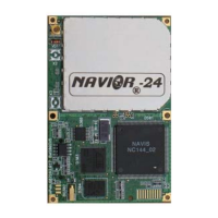
Figure I-1 NAVIOR-24S GPS/GLONASS receiver module ........................................................18
Figure I-2 Starter Kit front panel view ..........................................................................................20
Figure I-3 Starter Kit rear panel view ..........................................................................................21
Figure I-4 AC/DC Power Converter...............................................................................................22
Figure I-5 Starter Kit Interface Unit..............................................................................................28
Figure II-1 – Interface of serial port...............................................................................................32
Figure II-2 – Serial port connection ...............................................................................................38
Figure II-3 - Compact Magnetic-Mount GPS/GLONASS Antenna............................................42
Figure II-4 – Maritime GPS/GLONASS Antenna ........................................................................43
Figure III-1. The “1PPS” temporal diagram and digitizing, given out in the 72h package of
BINR protocol...................................................................................................................................47
Figure III-2. Temporal diagram of “1PPS” and its digitizing, given out in a $PALCTIM
report of NMEA protocol ................................................................................................................47
Figure IV-1. Interference mask immunity.....................................................................................63
Figure IV-2 Main Window. ...........................................................................................................135
Figure IV-3. Initial serial port settings.........................................................................................136
Figure IV-4. The Main Window after connection has been successfully established. .............137
Figure IV-5. Receiver Test window. .............................................................................................139
Figure IV-6. Receiver Test window with test results. .................................................................140
Figure IV-7. Software Revision window. .....................................................................................141
Figure IV-8. Connection Test confirmation message..................................................................142
Figure IV-9. BINR Settings window.............................................................................................143
Figure IV-10. Serial Port Settings window ..................................................................................145
Figure IV-11 . Port settings confirmation message. ....................................................................146
Figure IV-12. Shows the Main Preferences window. ..................................................................147
Figure IV-13. Changing Masks in the Main Preferences window.............................................149
Figure IV-14. SVs tracked window...............................................................................................150
Figure IV-15. Heading and Speed window. .................................................................................152
Figure IV-16. DOPs info window..................................................................................................153
Figure IV-17. Local Timezone window ........................................................................................154
Figure IV-18. Changing time offset in the Local Timezone window. ........................................155
Figure IV-19. SVs in view window................................................................................................156
Figure IV-20. Position and Velocity window ...............................................................................158
Figure IV-21. Last Position Solution window..............................................................................159
Figure IV-22. Extrapolated Position window ..............................................................................160
Figure IV-23. Receiver Channels Info window ...........................................................................161
Figure IV-24. Ionospheric Parameters window ..........................................................................164
Figure IV-25. UTC Parameters.....................................................................................................165
Figure IV-26. A confirmation request ..........................................................................................166
Figure IV-27. Restart type.............................................................................................................167
Figure IV-28. Started STOREGIS window .................................................................................202
Figure IV-29. The POSITION window ........................................................................................204
Figure IV-30. The STATISTIC window ......................................................................................205
Figure IV-31. The KINEMATIC window....................................................................................206