7197 Series II Owner’s Manual Chapter 5: Communication
August 2011
39
Connector
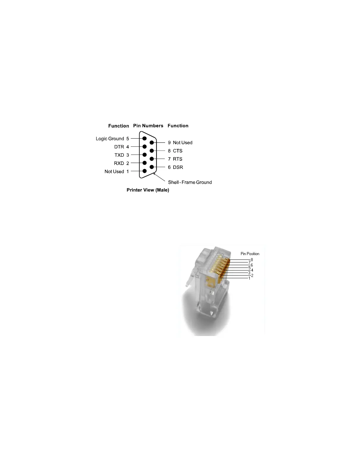
RS 232 Connector
The illustration shows the RS-232C communication connector and pin assignments. The
connector is a 9-pin male D-shell connector and is located in the hollow cavity under the
printer at the rear.
Ethernet Connector
The Ethernet I/F connector is a 8P8C modular connector (usually called RJ45) with the
following pin assignments:
1) Pin Position 1 – TX+
2) Pin Position 2 – TX-
3) Pin Position 3 – RX+
4) Pin Position 6 – RX-
DC Power Connector
The illustration shows the power cable connector and pin assignments. The power cable connector is
a 3-pin DIN plug and is located in the hollow cavity under the printer at the rear.
 Loading...