7197 Series II Owner’s Manual Chapter 5: Communication
August 2011
41
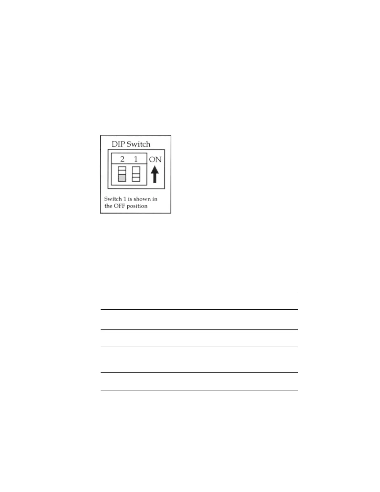
Switch Settings
The DIP switches are located on the PC board at the back of the printer as shown in the
illustration in “Level 1 Diagnostics” in chapter 4.
The switches are used to put the printer into various modes for printer configuration set
up.
Use a paper clip or other pointed object to set the switches.
1. Set the switches to the desired settings shown in the table.
Caution: Do not set switch 1 to On. Setting switch 1 to On puts the printer in level 1
diagnostics (setup mode) where other functions and tests can be changed.
DIP Switch Settings
Switch 1
Setting
Switch 2 Setting Printer State
OFF (0) OFF (0)
On-line Mode (default)
(In Ethernet I/F : Manual IP)
ON(1) OFF (0)
Diagnostic Mode
OFF (0) ON (1)*
Flash Download Mode / Vendor
Adjustment Mode
ON (1) ON (1)
On-line Mode
(In Ethernet I/F : DHCP IP)
* It is optional to set this switch to ON when reflashing the IPL firmware.
Printer End View
 Loading...