Chapter 1: Getting Started 1-11
ThetablesbelowlisttheindicationandcauseoftheLEDillumination
andbeepsforthebase.
ion SystemStatusIndicator(RedLED)
SystemCondit
PowerOn/Diagnostic
Error
BlinkLEDforlongduration,
pulsingindefinitely
ReceivingData
BlinkLEDforshortdurationin
multiplepulses.Occurswhile
transferringdatato/fromtheRF
moduleortheHostport.
Note: Chargingonlyoccurswithexternalpowerappliedtothebase
or12voltHostpower.
Charge
Condition ChargeStatusIndicator(GreenLED)
Scannerinsertedinto Threeflashes
>80%char
ed Oncontinuousl
30%to80%char
ed Slowflash
1secondon
1secondof f
<30%charged Fastflash,300 mSecon,300mSecoff
Basic Operation
sthe
er
menuing,visualindicatorsupport,power‐ondiagnostics),anddata
translationrequiredforthehostsystem.
of the Cordless System
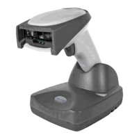
Cordless Base
Thecordlessbaseprovidesthelinkbetweenthecordlessscannerand
thehostsystem.ThebasecontainsaninterfaceassemblyandanRF
communicationmodule.TheRFcommunicationmoduleperform
dataexchangebetweenthecordlessscannerandtheinterface
assembly.Thecontrolassemblycoordinatesthecentralinterface
activitiesincluding:transmitting/receiving
commandsanddata
to/fromthehostsystem,performingsoftwareactivities(paramet
 Loading...