EasyManua.ls Logo

Neoway N75 - Figure 3-1 Current Peaks and Voltage Drops (GSM;GPRS); Figure 3-2 Recommended Design 1

Neoway N75
95 pages
Print Icon
To Next Page IconTo Next Page
To Previous Page IconTo Previous Page
Loading...
N75
Hardware User Guide
Copyright © Neoway Technology Co., Ltd
15
Figure 3-1 Current peaks and voltage drops (GSM/GPRS)
Keep voltage above 3.3V
3.3V
0 ms
3.7 ms 7.4 ms 10.7 ms
T
Imax 2A
Voltage
Input
current
3.8V
min
max
0.577ms 2.308ms
The power supply design covers two parts: schematic design and PCB layout.
Schematic Design
Design the circuit of the power supply for N75 based on the input voltage you choose.Generally there
are three types of input voltages:
3.3V-4.3V (3.8 V typically, output by battery)
4.3V-5.5V (5.0V typically, output by rectifier inside a computer)
5.5V-24V (12V typically, output by vehicle battery)
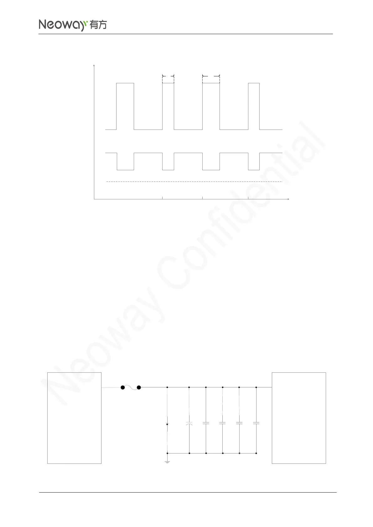
Figure 3-2 shows schematic design recommended for 3.3V-4.3V input.
Figure 3-2 Recommended design 1
Power Supply
N75
Module
TVS
C1 C2 C3 C4
Close to the pin of the module
VBAT
Test point
I_max
C5

Table of Contents

Related product manuals