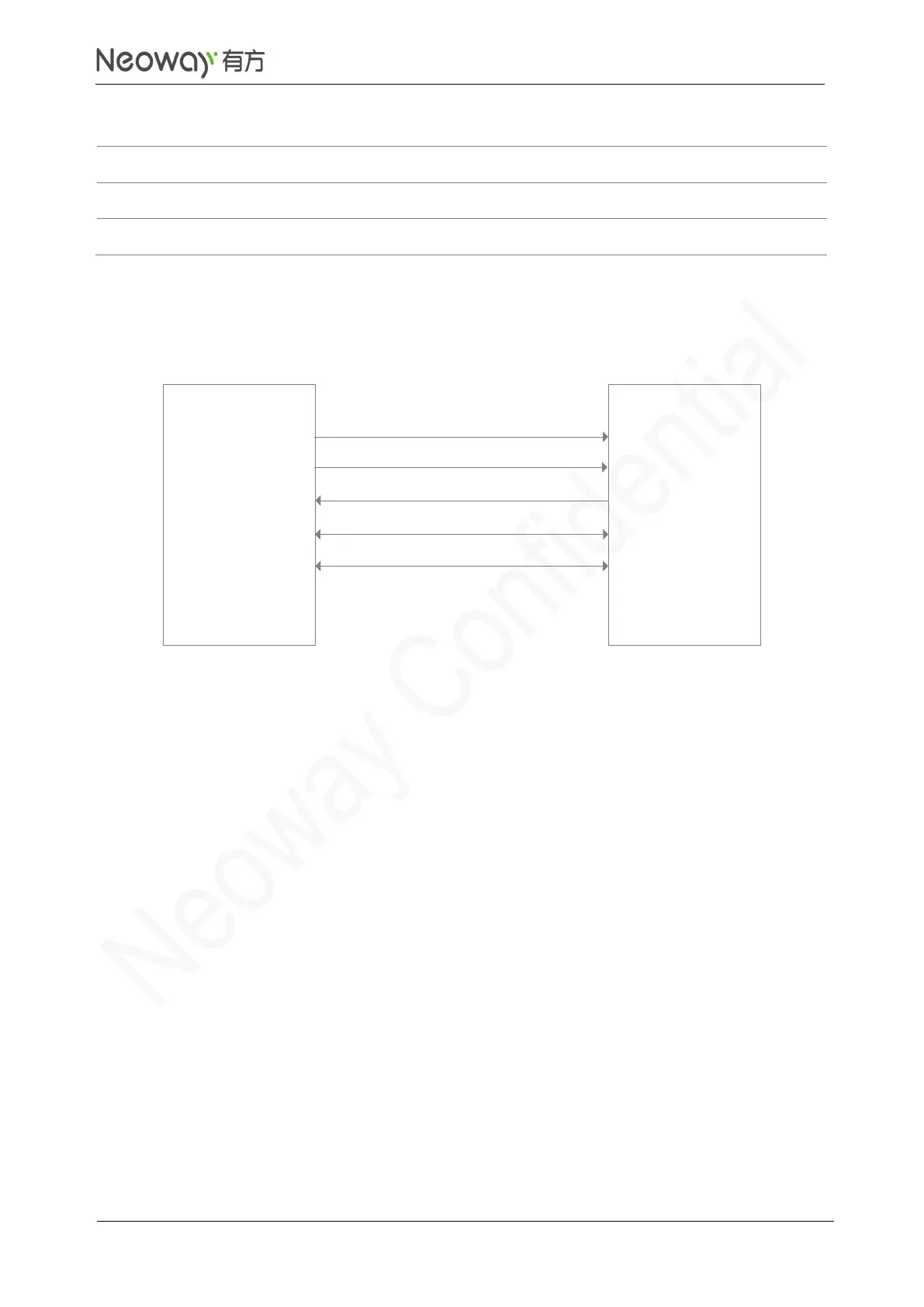
N75 provides one I2S/PCM multiplex interface that supports 1.8V. Figure 3-24 shows I2S connection.
Figure 3-24 I2S connection
Schematic Guidelines
⚫
If the levels of N75 and CODEC do not match, add a level shift circuit as shown in 3.3.4.
⚫
Leave I2S_MCLK floating in your application if it is not required for the CODEC chipset selected.
PCB Design Guidelines
⚫
Do not cross other traces if possible. If crossing is inevitable, route the I2S traces perpendicular
to other traces.
⚫
Keep I2S traces far away from areas that might introduce ESD.
⚫
Surround I2S_MCLK signal traces with ground.
The I2S function complies with Phillips I2S Bus Specifications revised June 5, 1996.