⚫
If the UART does not match the logic voltage of the MCU, add a level shifting circuit outside of
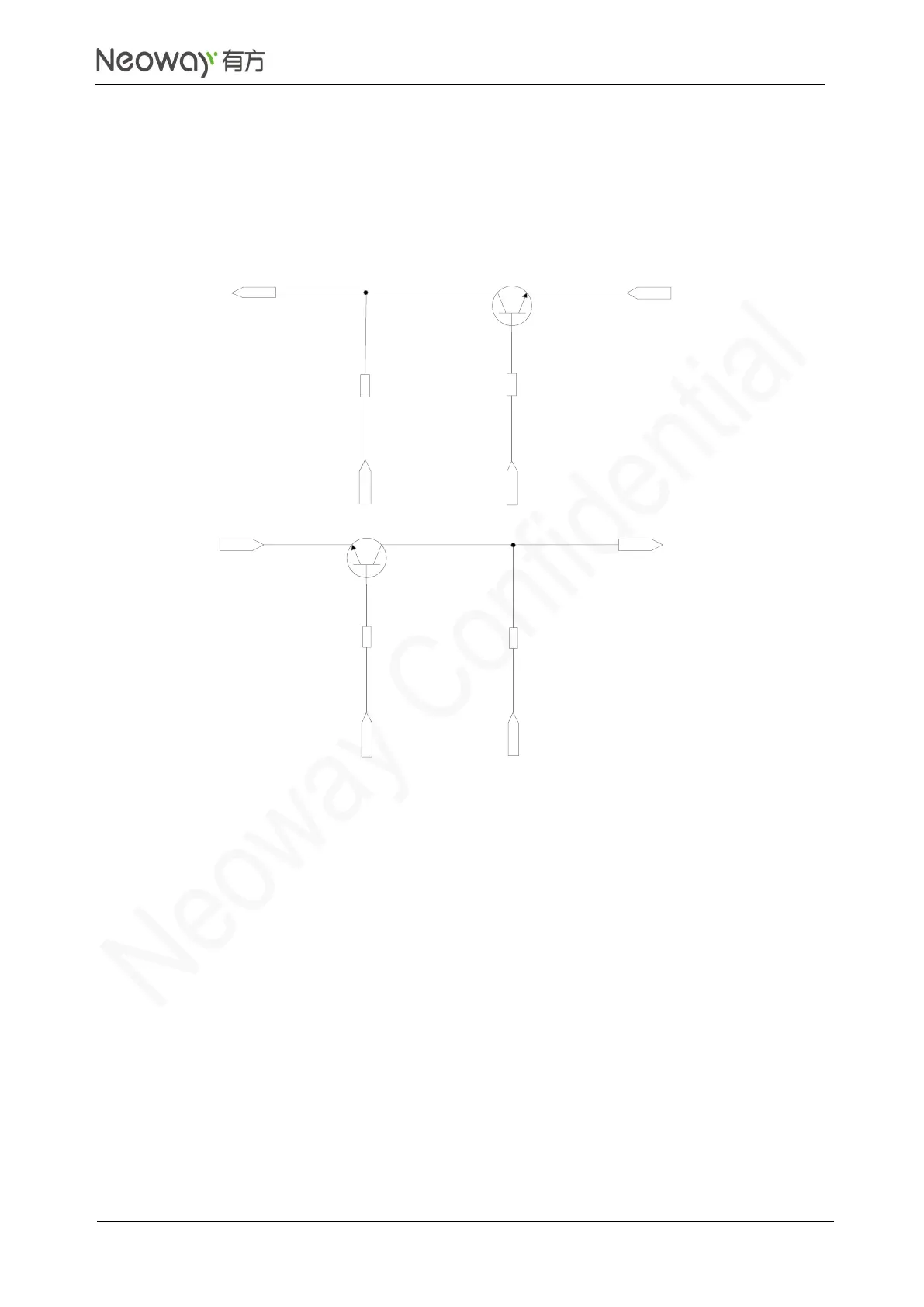
the module. Three types of level shifting circuit is recommended based on the logic level quality.
If the low level at MCU_UART (V
IL
) is lower than 200mV, adopt recommended level shifting circuit 1.
Figure 3-18 Recommended level shifting circuit 1
If the low level at MCU_UART (V
IL
) is lower than 200mV, adopt recommended level shifting circuit 2.
Otherwise, low level at UART might be higher than required, resulting in failure to identify signals.