Schematic Guidelines
⚫
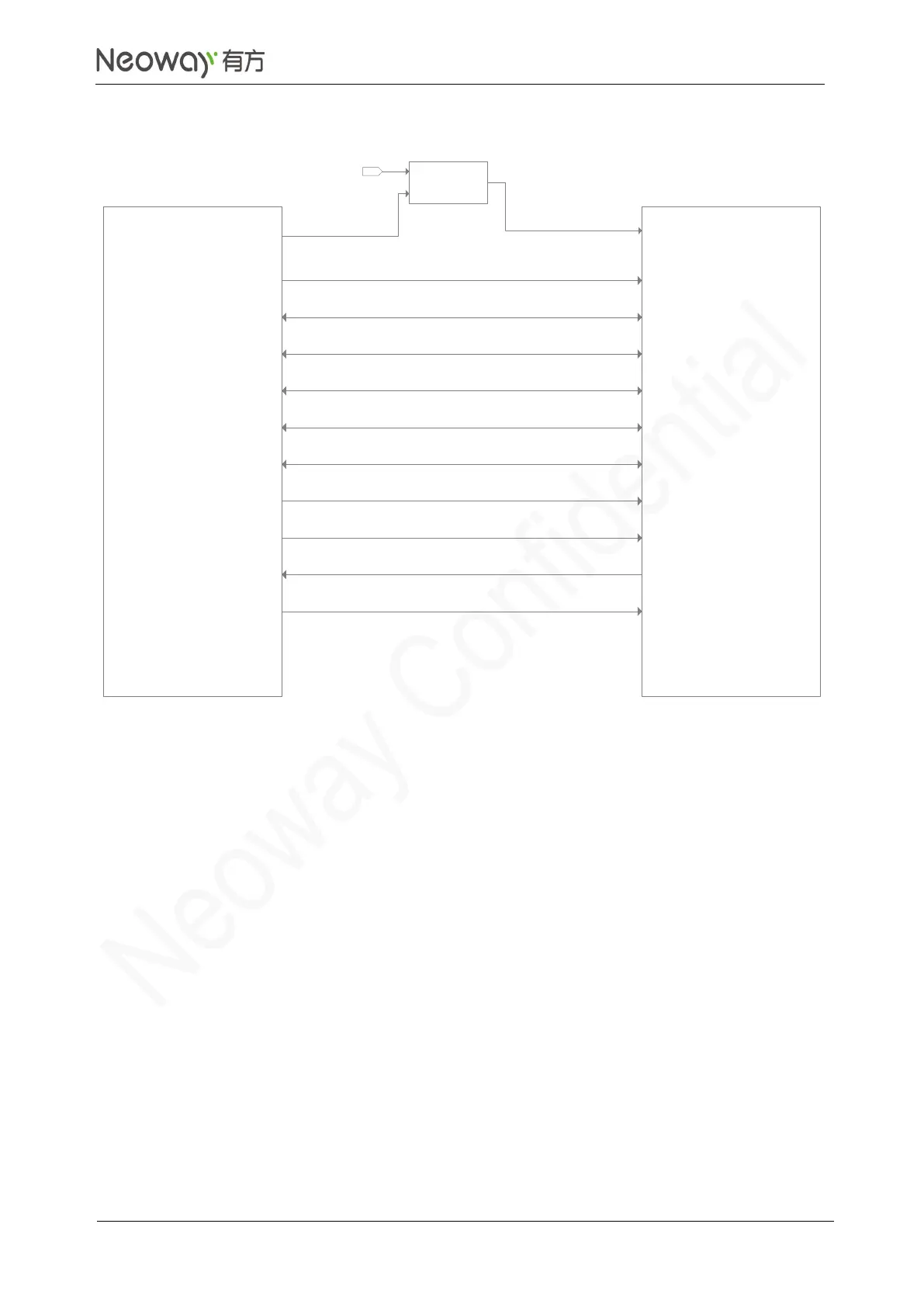
If the WLAN chipset requires that DATA trace be connected to a power supply through a pull-up
resistor, the power supply can be VDD_1P8 of the module and the pull-up resistor uses the
recommended values.
⚫
WLAN/LTE co-exist interface is used for 2.4 GHz WLAN frequency band and LTE high
frequency, which overlap so they might affect each other. It is recommended to use this function
if the WLAN chipset supports it.
⚫
The frequency of WLAN_SLEEP_CLK is 32.768 KHz. If the trace is too long, add an RC circuit
to adjust the wave shape.
⚫
WAKE_ON_WIRELESS is the communication control signal in WLAN mode. Operating at 1.8 V,
this pin is an open-drain output. Leave this pin floating if the WLAN chipset does not support this
function.
PCB Design Guidelines
⚫
SDIO interface requires control of trace length. For details about the requirements, refer to the
WLAN chipset spec.