host mode only. Its feature parameters and connection are shown in the following table and figure.
Table 3-10 I2C feature parameters
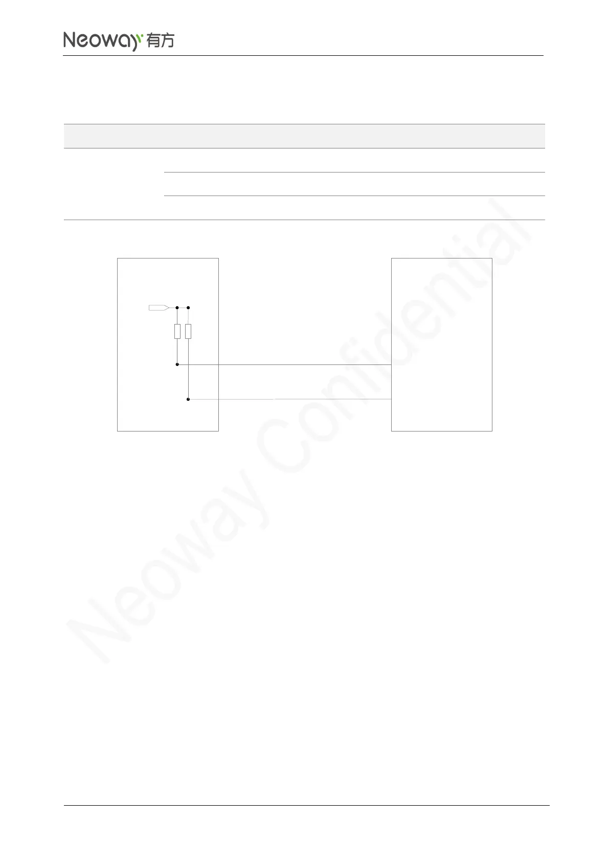
Schematic Guidelines
⚫
If the levels of slave I2C device and N75 do not match, add a level shifting circuit. Refer to
Figure 3-20.
⚫
Some pins can be multiplexed for I2C function. Connect external pull-up resistors to these pins
when they are used for I2C function. For details, see section 3.7 MUX Interfaces.
PCB Design Guidelines
⚫
Do not cross other traces if possible. If crossing is inevitable, route the I2C traces perpendicular
to other traces.
⚫
Keep I2C traces far away from areas that might introduce ESD.
⚫
Surround signal traces with ground.
The following figures and tables show the I2C data transmission, I2C timing, and parameters.