EasyManua.ls Logo

Neoway N75 - Control Interfaces; Pwrkey_N; Figure 3-6 Reference Design of Startup Controlled by Button; Table 3-1 VDD_1 P8 Electrical Features

Neoway N75
95 pages
Print Icon
To Next Page IconTo Next Page
To Previous Page IconTo Previous Page
Loading...
N75
Hardware User Guide
Copyright © Neoway Technology Co., Ltd
19
protector should be added.
Table 3-1 VDD_1P8 electrical features
Parameter
Minimum
Typical
Maximum
Remarks
Output Voltage
1.76V
1.8V
1.84V
Temperature range: -40°C ~ +85°C
Output Current
50 mA
Do not use this pin to load any components.
3.2 Control Interfaces
Signal
Pin
I/O
Function
Remarks
RESET_N
32
DI
Module reset input
Reset at low level
PWRKEY_N
33
DI
ON/OFF button
Triggered by low level (recommended)
N750 provides PWRKEY_N and RESET_N to power up and reset the module respectively.
3.2.1 PWRKEY_N
N75 allows startup by the following controls:
Button
MCU
The values of R1 and R2 are determined by the IO domain of MCU. The voltage across the base
of the triode should not exceed 1.8V.
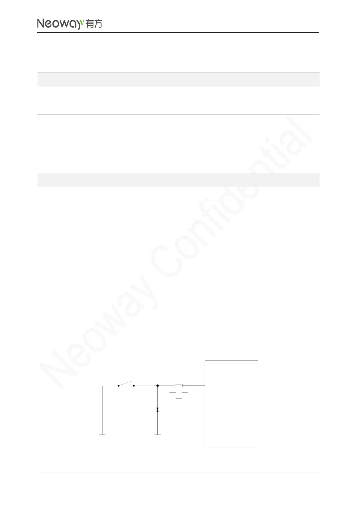
Automatic startup after powered up
Figure 3-6 Reference design of startup controlled by button
ESD
N75
module
PWRKEY_N
S1
R1
1kΩ

Table of Contents

Related product manuals