3.8.5 USB_BOOT
Pin 48 is also the USB_BOOT pin in addition to WCT_LTE_RXD. It is the last method to handle issues
that result in startup or running failures.
Connect USB_BOOT to VDDIO_1P8 through a pull-up resistor transiently after the module is started,
and the module will enter forcible download mode.
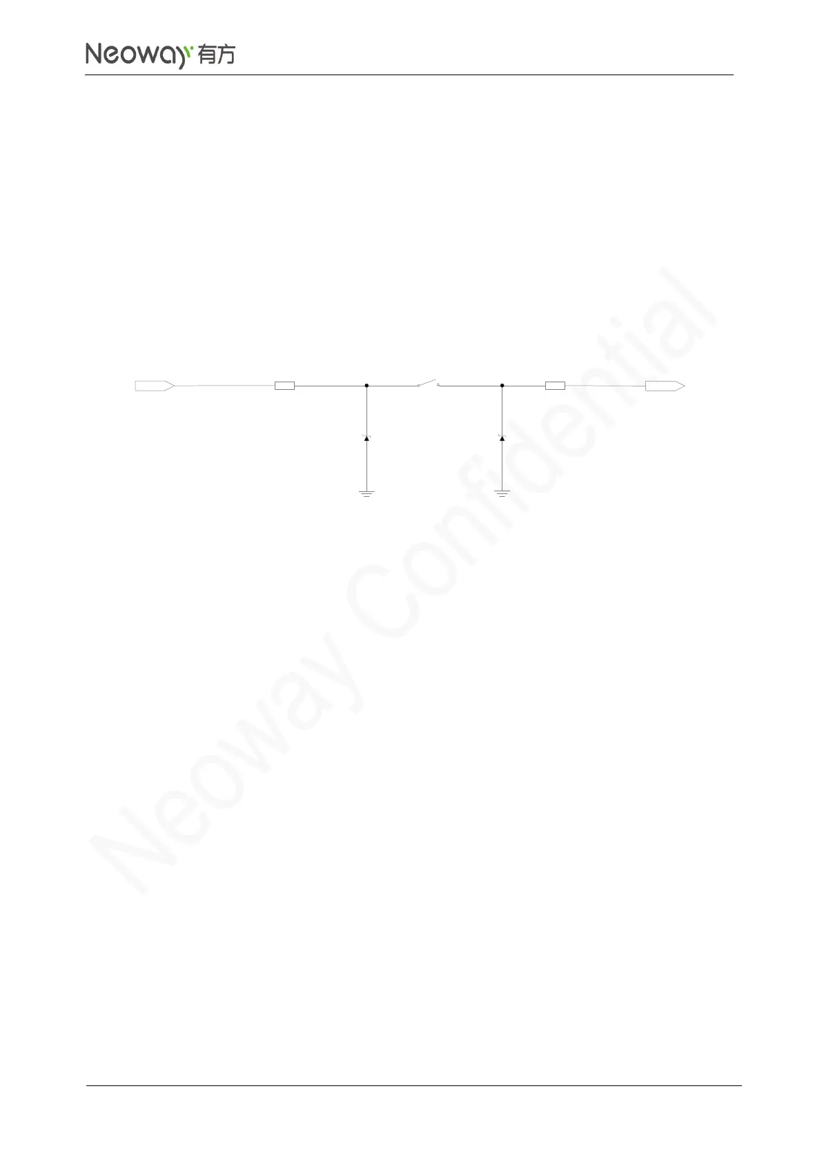
Reserve this pin to facilitate software upgrade and debugging. Figure 3-62 shows the reference design
of this pin.
Figure 3-62 Reference design of USB_BOOT